

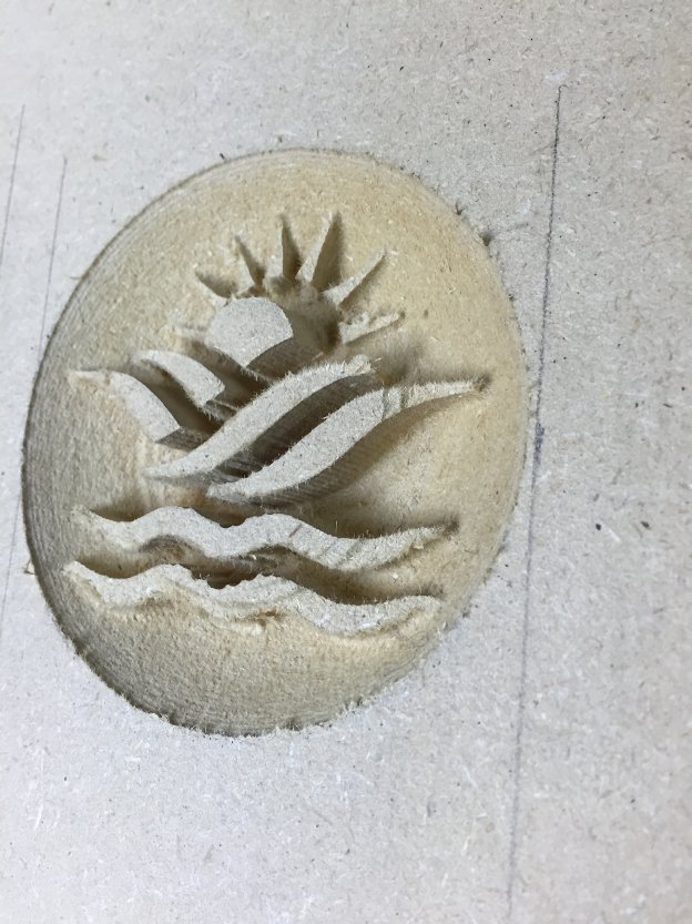
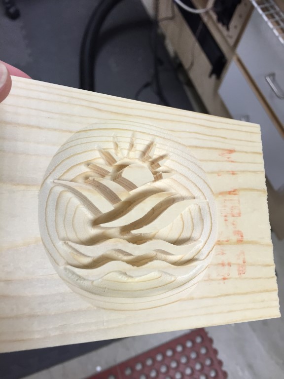
After setting up my CNC and running some tests and jobs I was quickly realizing that I was having problems with my Z axis losing steps. I was working on a carving and noticing the cuts were not consistent, my first clue. The image below was from a sample I ran, as it got further into the job I was noticing that the Z axis was retracting correctly and hence ruining the job.
After running some more tests I finally decided to rebuild my Z axis and would try to use the CNC to do it. Since it wasn’t going to be highly detailed I wasn’t as concerned about the Z problem and losing steps.
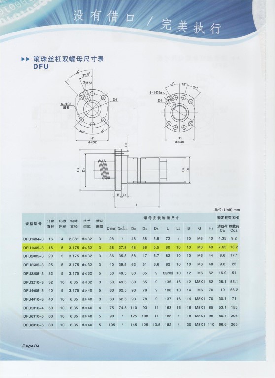
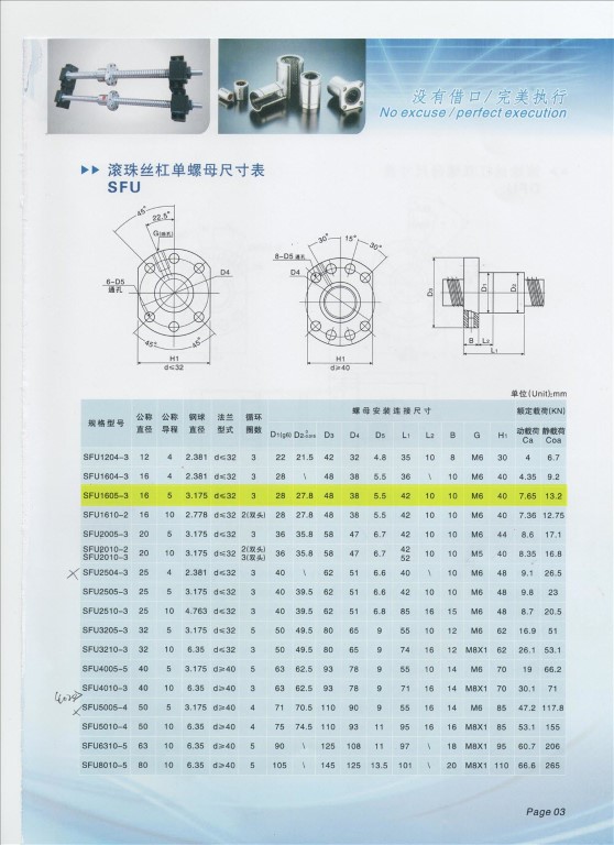
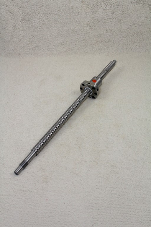
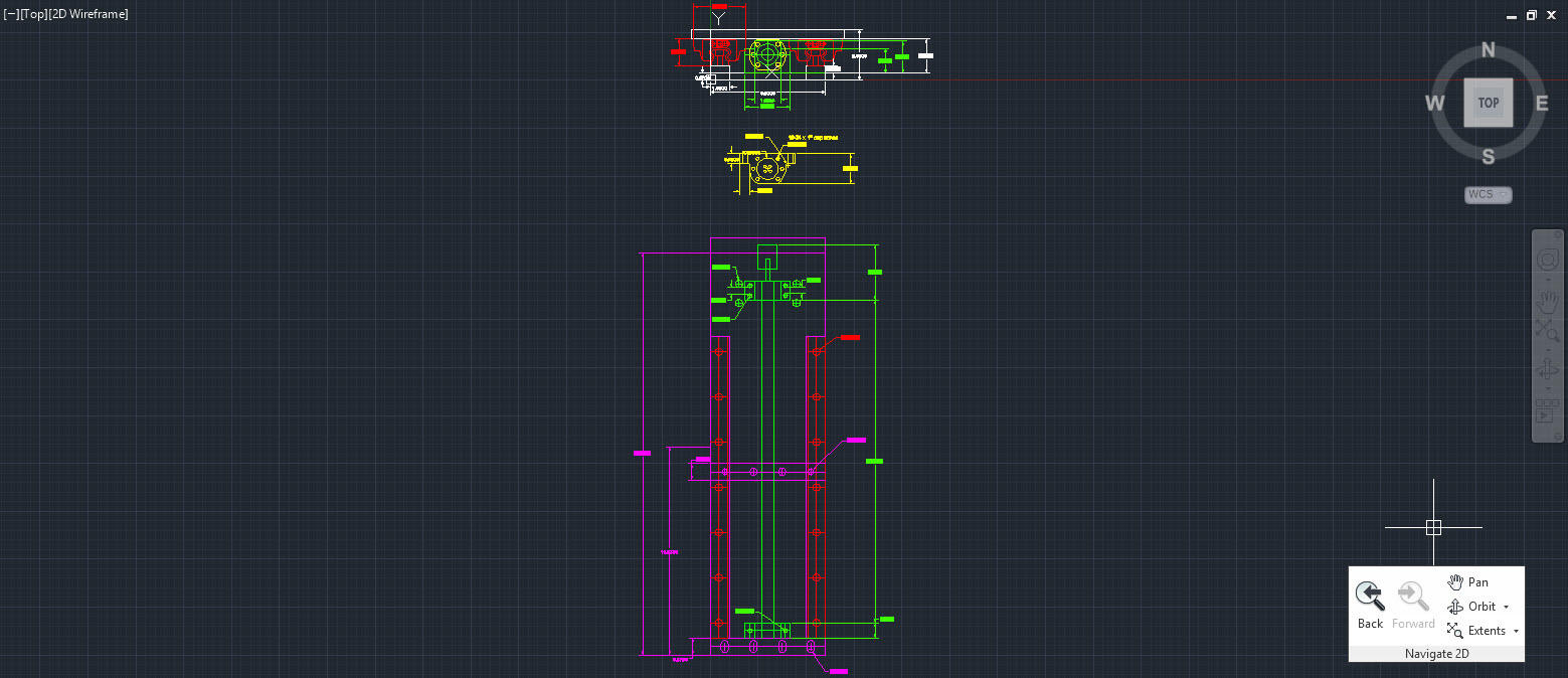
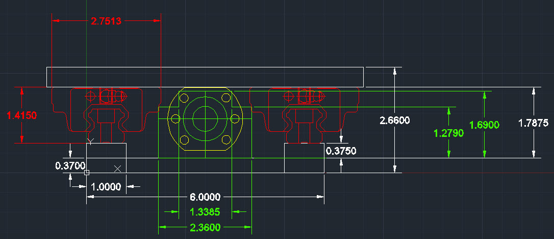
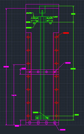
So, I went looking around the internet and found a ball screw off of E-Bay from China.. go figure. Anyway it was extremely affordable, right at $100 shipped so how could I go to wrong. I found the specs and dimensions ans started drawing it up in AutoCad
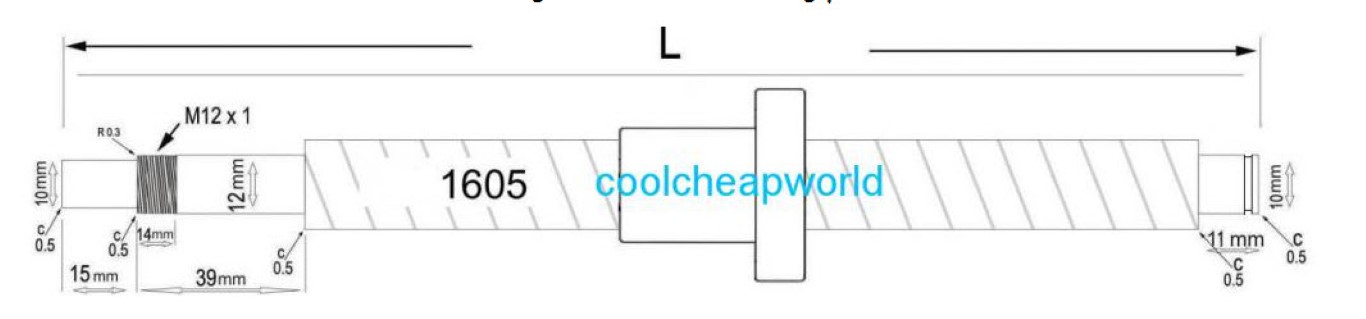
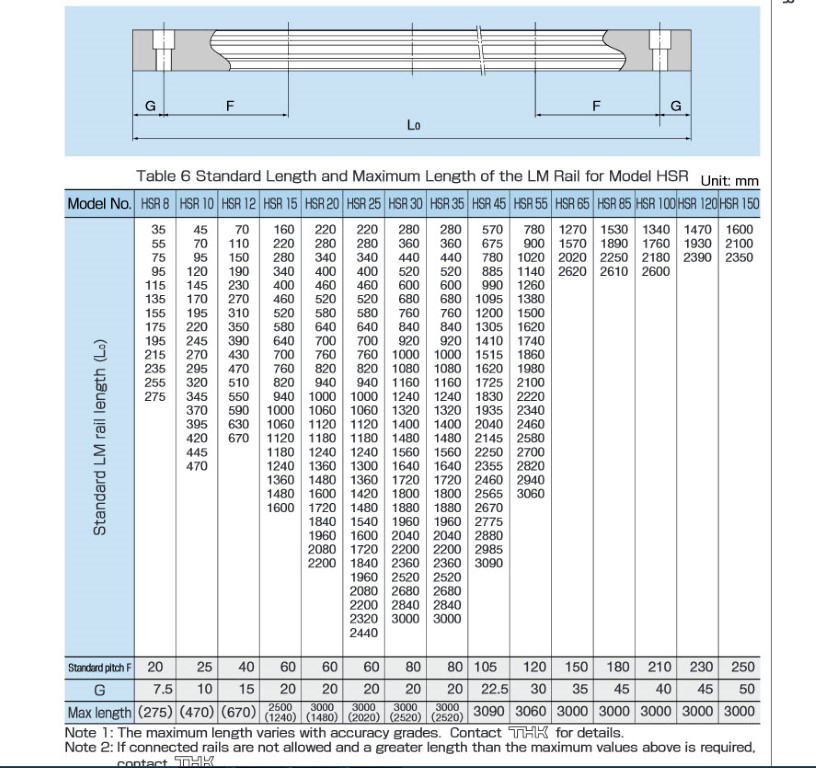
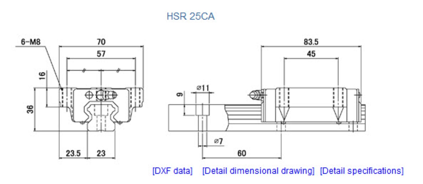
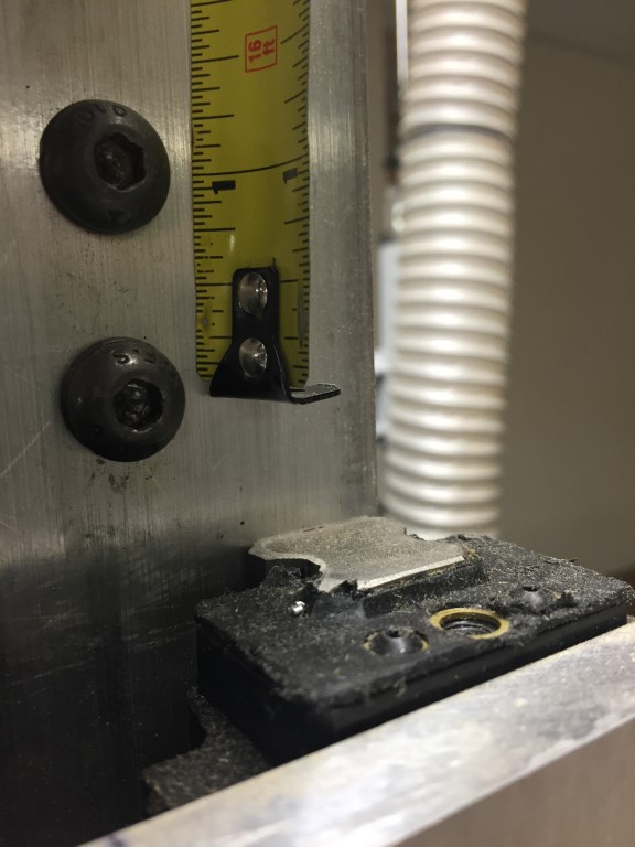
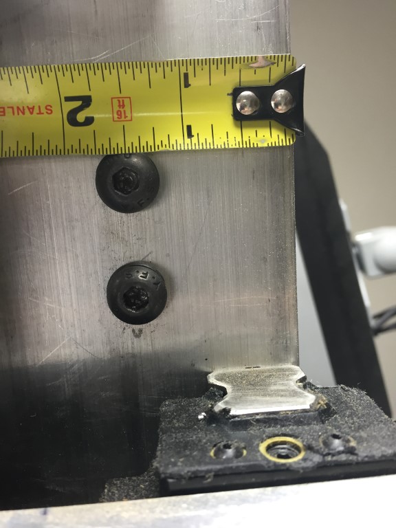
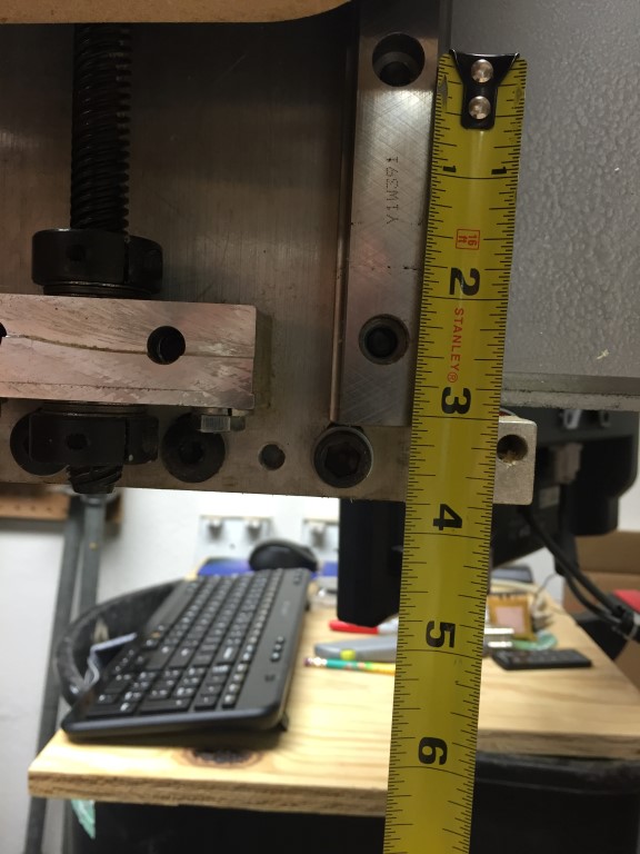
Since I was retrofitting the new Z I needed to make sure it would fit so measure, measure, measure.. I needed to make sure the ball screw would fit between the back plate and the Z plate since I wanted to continue to use the linear slides that I currently had. From what I figured out, the only way that was going to happen was if I shimmed the linear rails off of the back plate, the ball screw was simply too large to tfit.

Here are the CAD drawings if your interested in them..(New Z Plate Download)
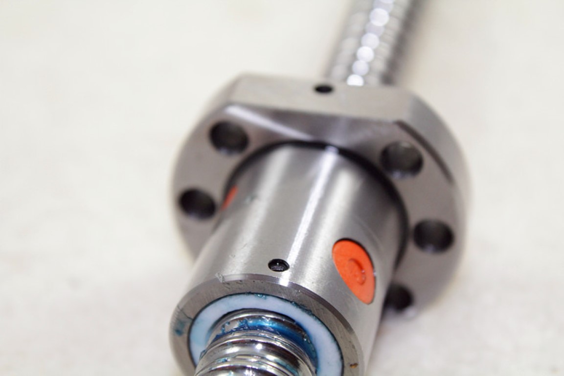
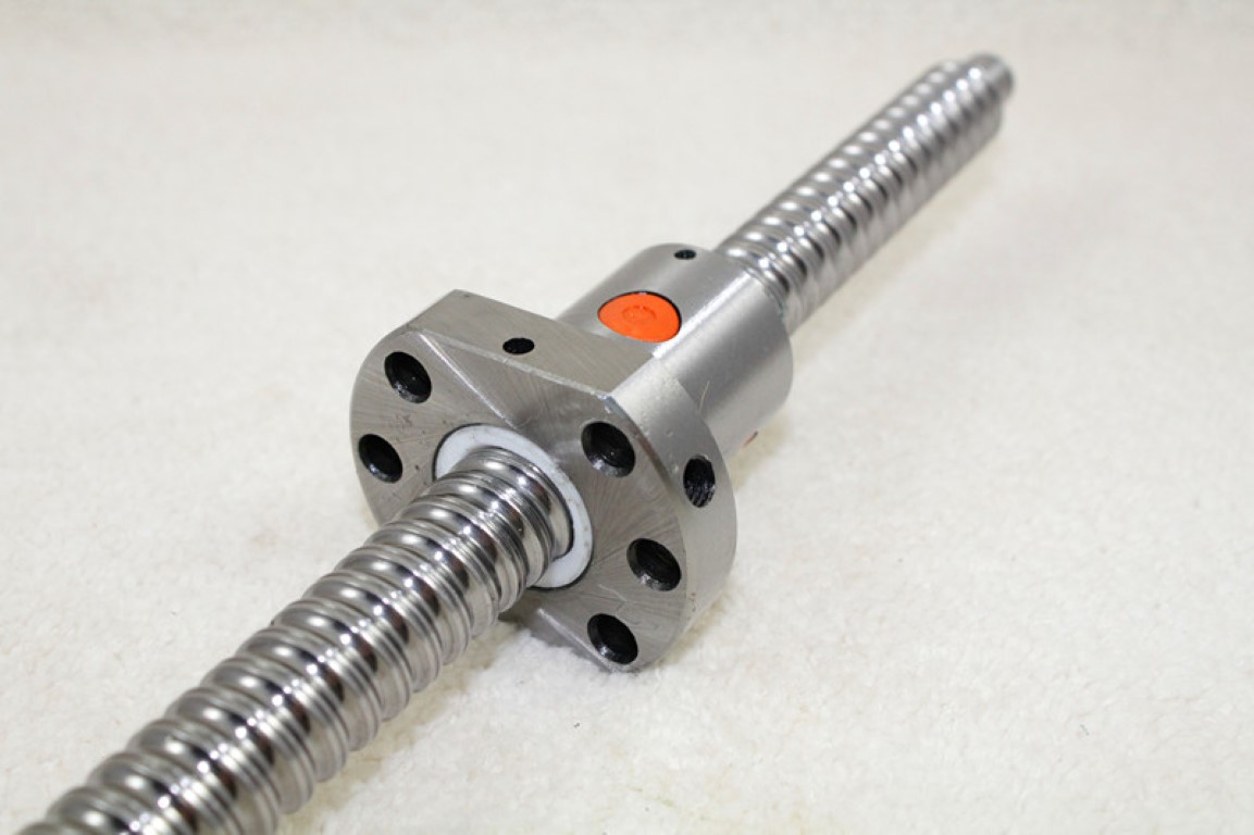
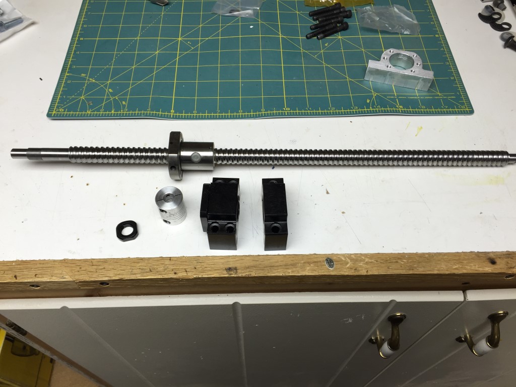
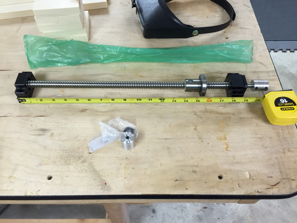
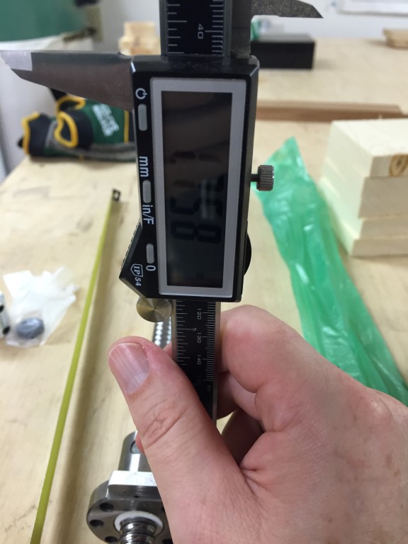
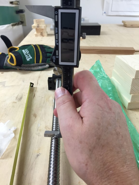
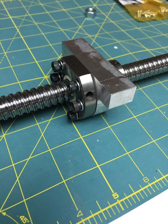
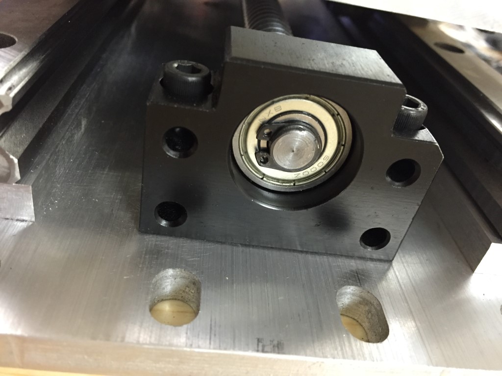
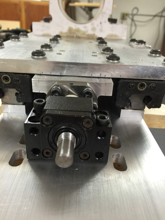
Well the Z axis parts finally arrived, actually they arrived faster than I thought they would. Everything looks good, 2 pillow blocks, 2 couplers, jam nut, anti-backlash nut and ball screw.
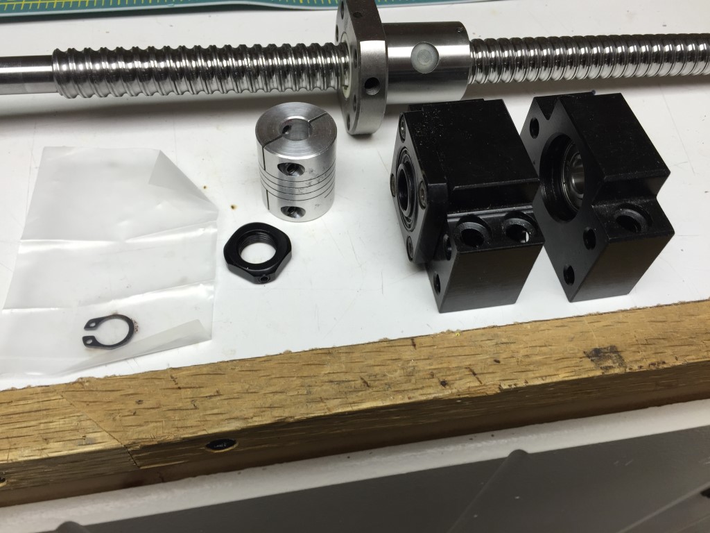
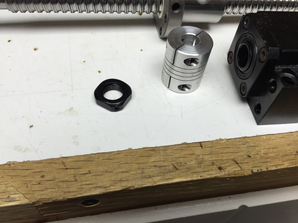
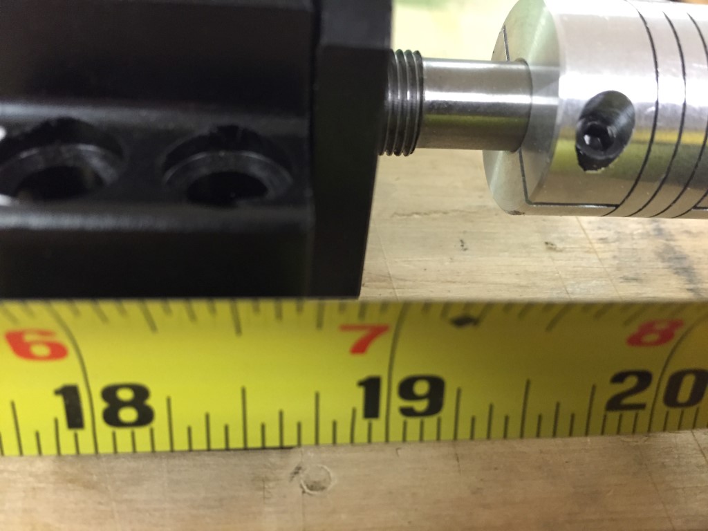
I had to make 1 modification the the ball screw and that was to grind a flat spot on it for the coupler to lock against, for a more secure set. I just pulled out my hand grinder and went at it.

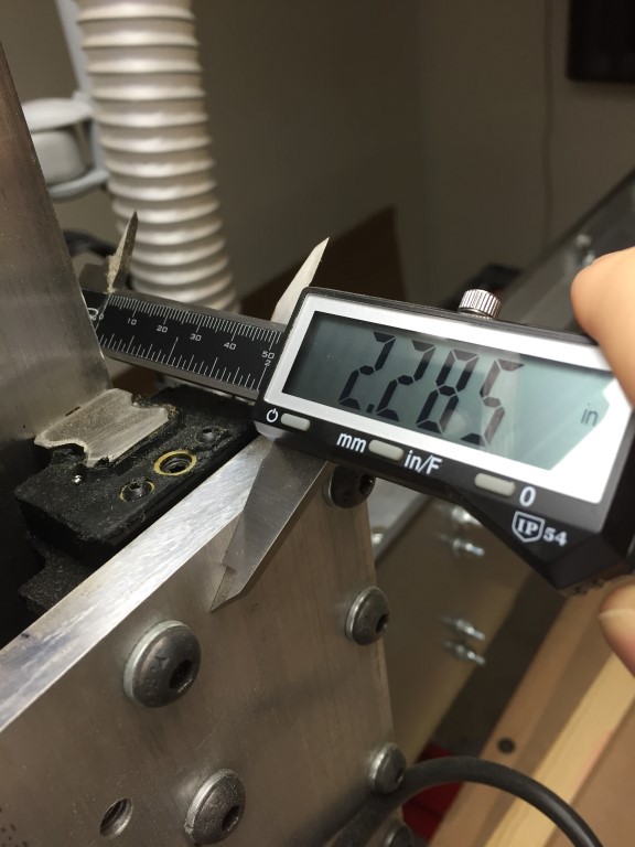
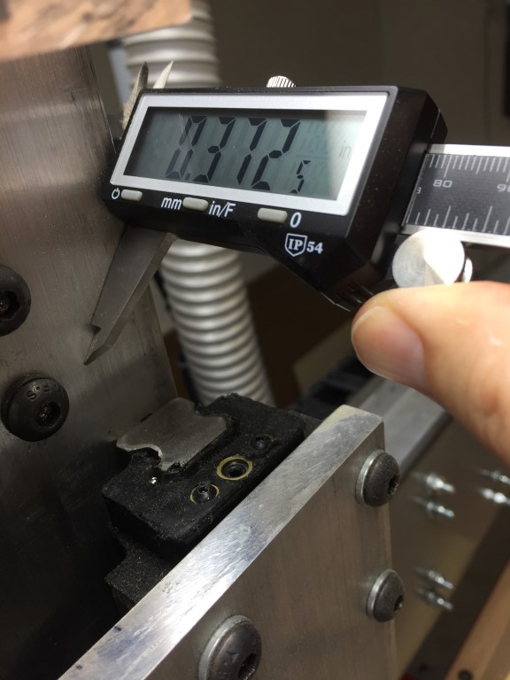
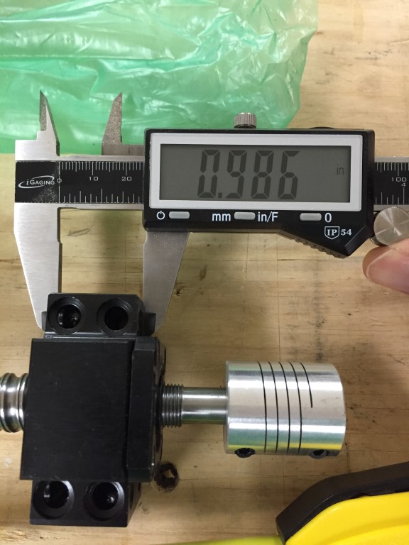
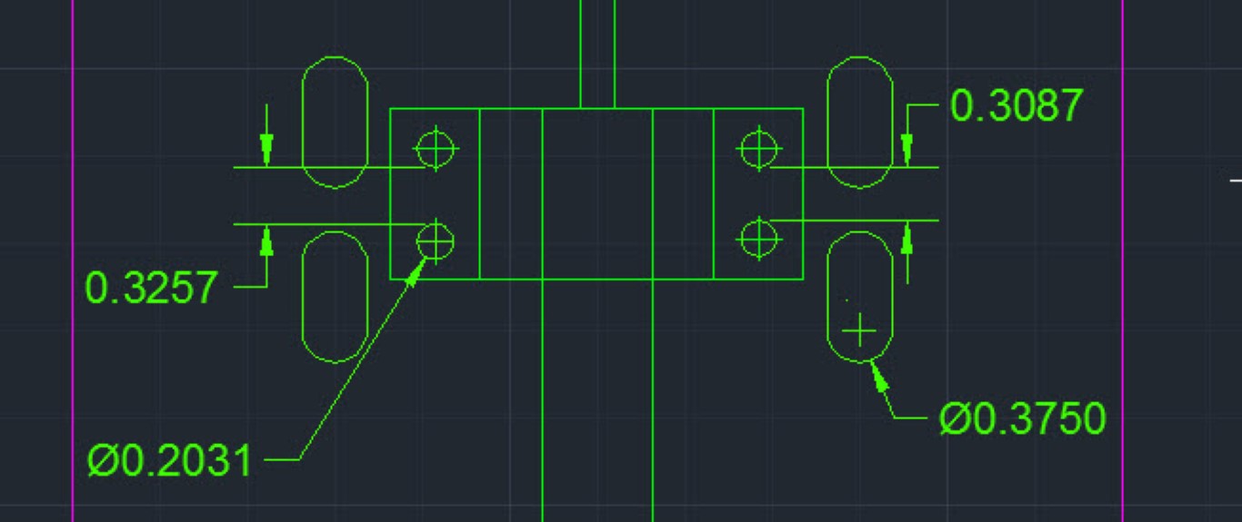
I wanted to verify the measurements matched up to what the spec sheet had and in general all looked good except for one of the pillow blocks.
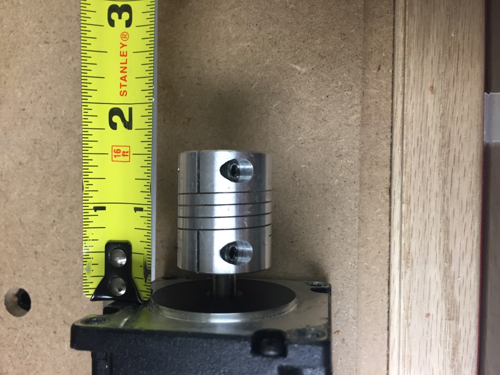


The top pillow block mounting holes were not drilled correctly, so I modified my drawing accordingly.
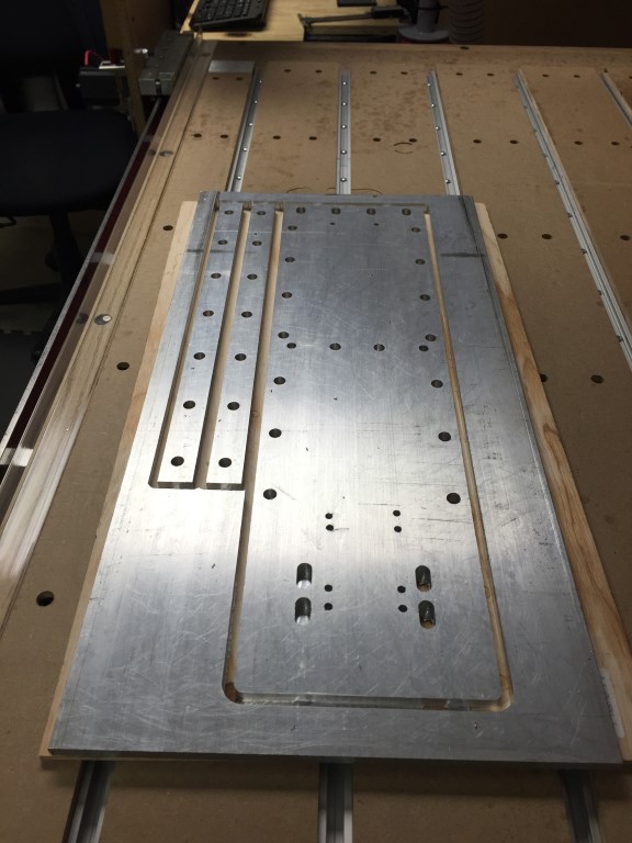
I created my tool paths in MasterCam and generated the G-Code then ran a test piece on some 1/4″ plywood just to be sure I drew it correctly. All looked good and off to the CNC I went with a piece of 3/8 aluminum and my drawings. Sorry, no video or drawings of the milling process since it was first attempt at a larger aluminum cut.
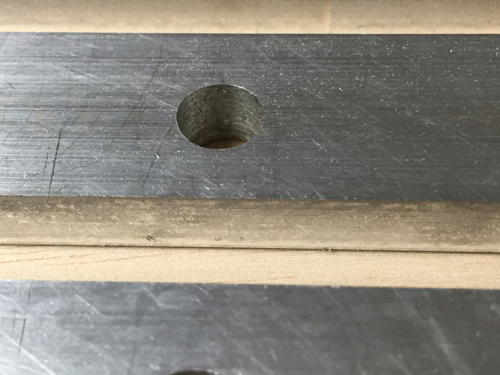
Since my table is made of MDF and I needed some cutting fluid for cutting aluminum I came up with an idea to use plastic to cover the surface. Lowe’s sells a roll of sticky backed plastic sheeting for covering flooring when doing remodeling, etc. and that was perfect for this job. I covered the top, bolted down the aluminum plate, set the 0.0 reference and the Z height and sprayed on some lubricant, WD-40.The CNC did a great job at cutting the plate but there are some improvements that need to happen, chip removal and a misting system of some kind. It was quite a pain in the rear to keep spraying WD-40 and the cutter was re-cutting old chips, not optimal.
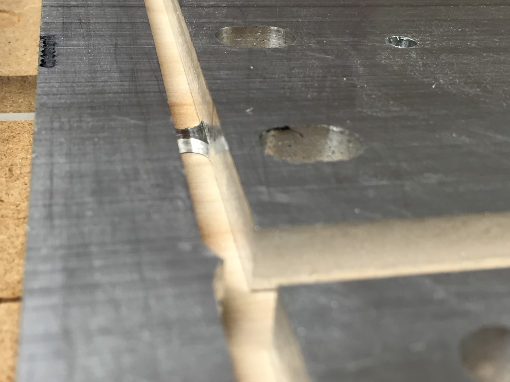
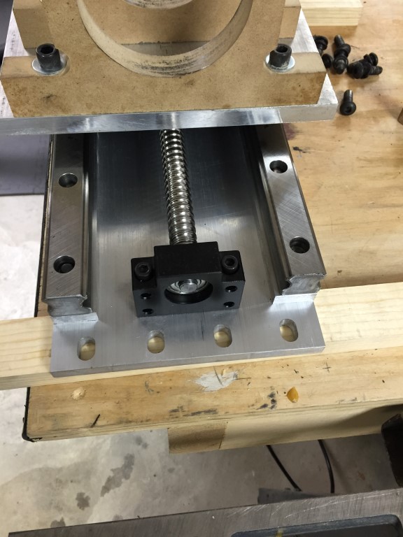
I then cut the anti-backlash nut holder out of 3/4″ aluminum using the same procedure above with WD-40. I fit perfectly, very cool…
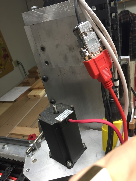
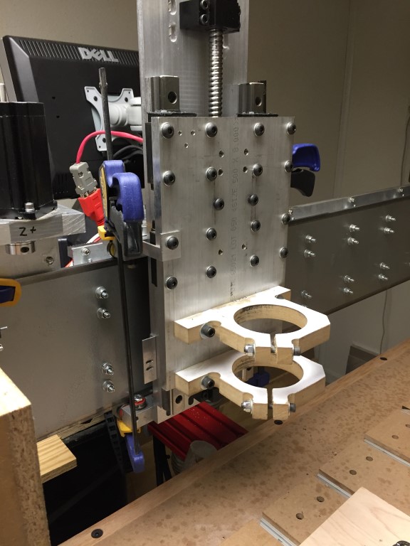
I had to tap some of the holes in the back plate and then it was ready for a trial fit. I can’t tell you how easy this was to assemble with the parts cut accuratly as opposed to had cutting them on the original build, very cool!
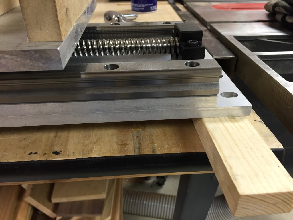

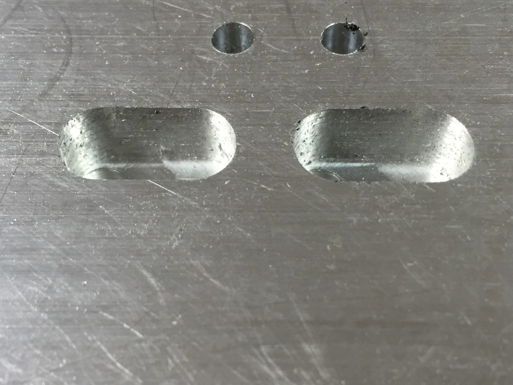
Slotted holes for adjusting were an excellent idea for removing any major play when bolting the plate back on the machine.
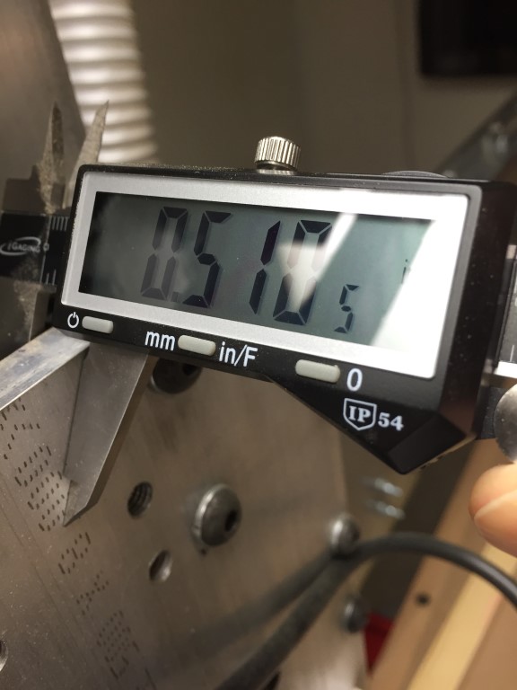
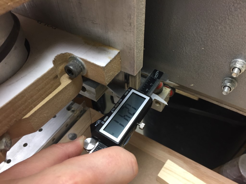
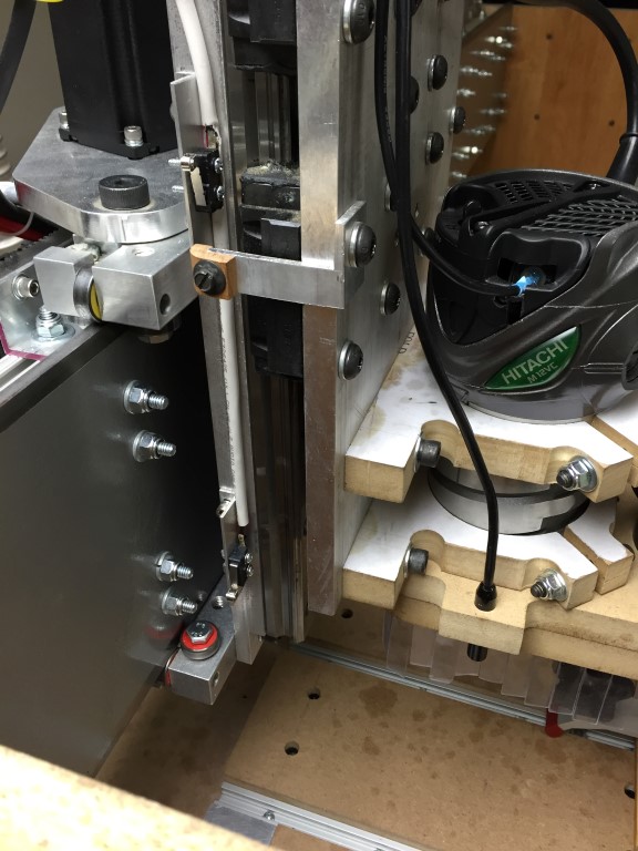
After the Z was fully assembled I tested the thickness needed between the anti-backlash nut holder and the movable plate on the Z axis and it was within .005 of an inch accurate, not bad for a home made CNC.
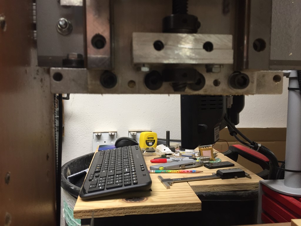
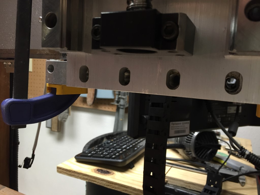
All back together…
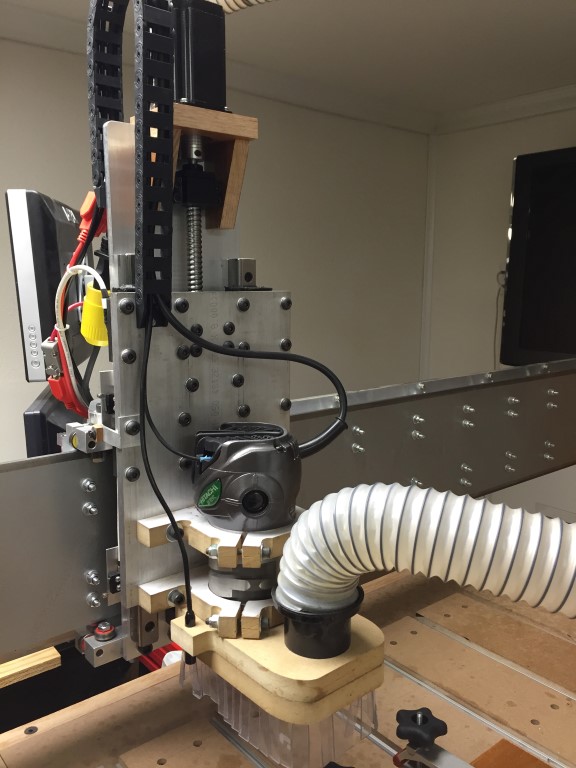
And the final test…
If I was able to help you figure out and fix your problem, buy me a beer! and Thanks..
![]()