

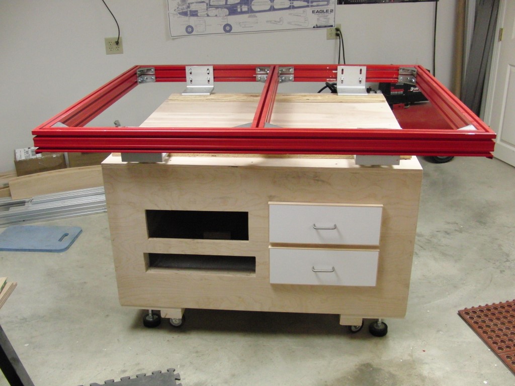
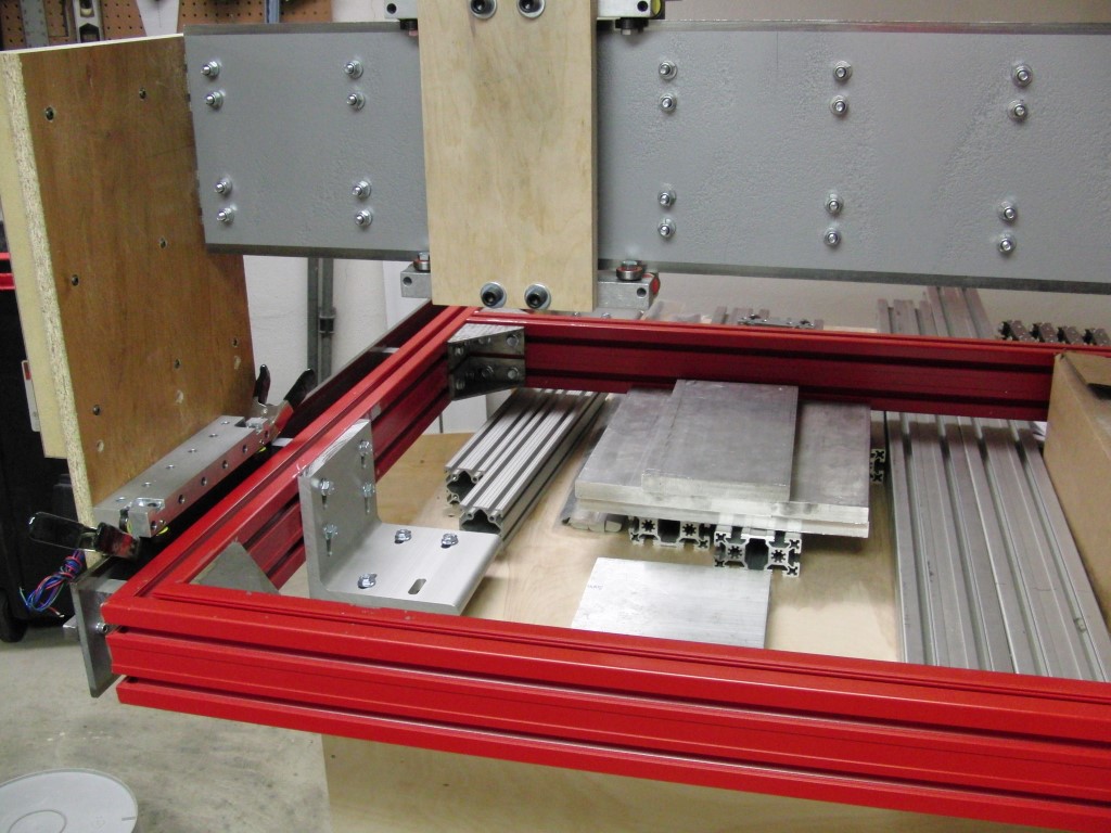
The build is going to be using 45×90 BOSCH Rexroth, the table size is 48 x 60 and will utilize rack and pinion movement. I plan on using a Hitachi MV2 router as the motor.
I’m still a bit undecided about the base but am leaning towards a cabinet with storage and will be elevated from the base for easier cleanup.
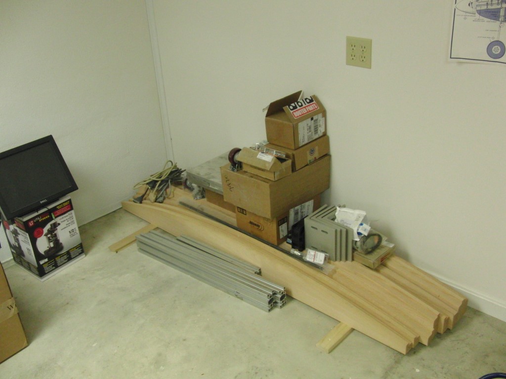
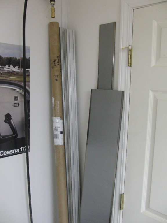
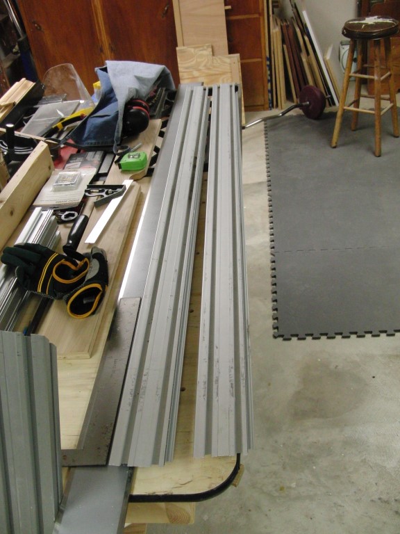
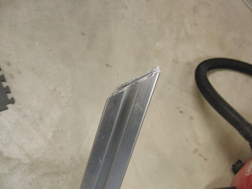
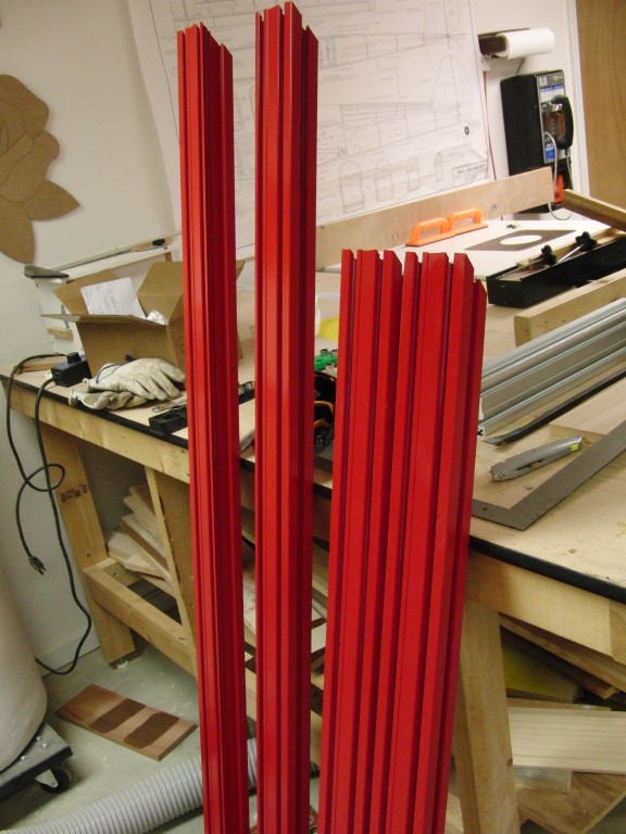
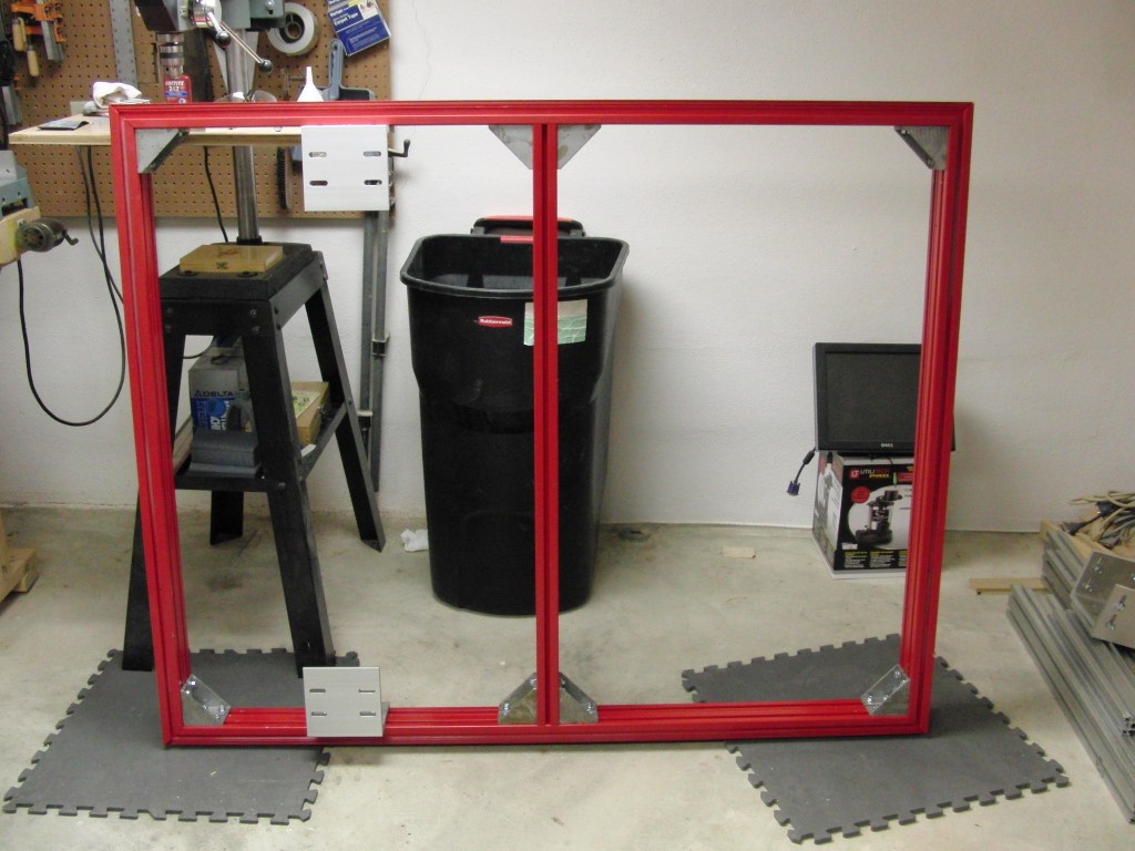
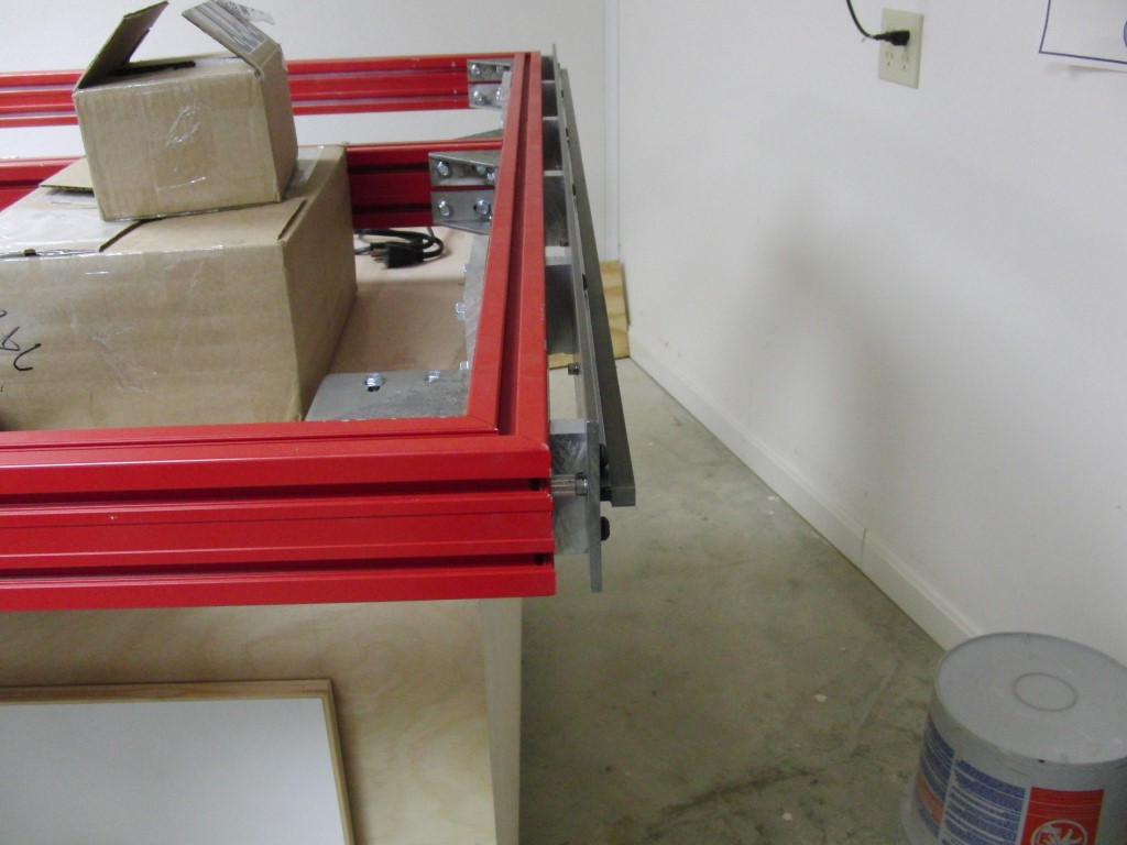
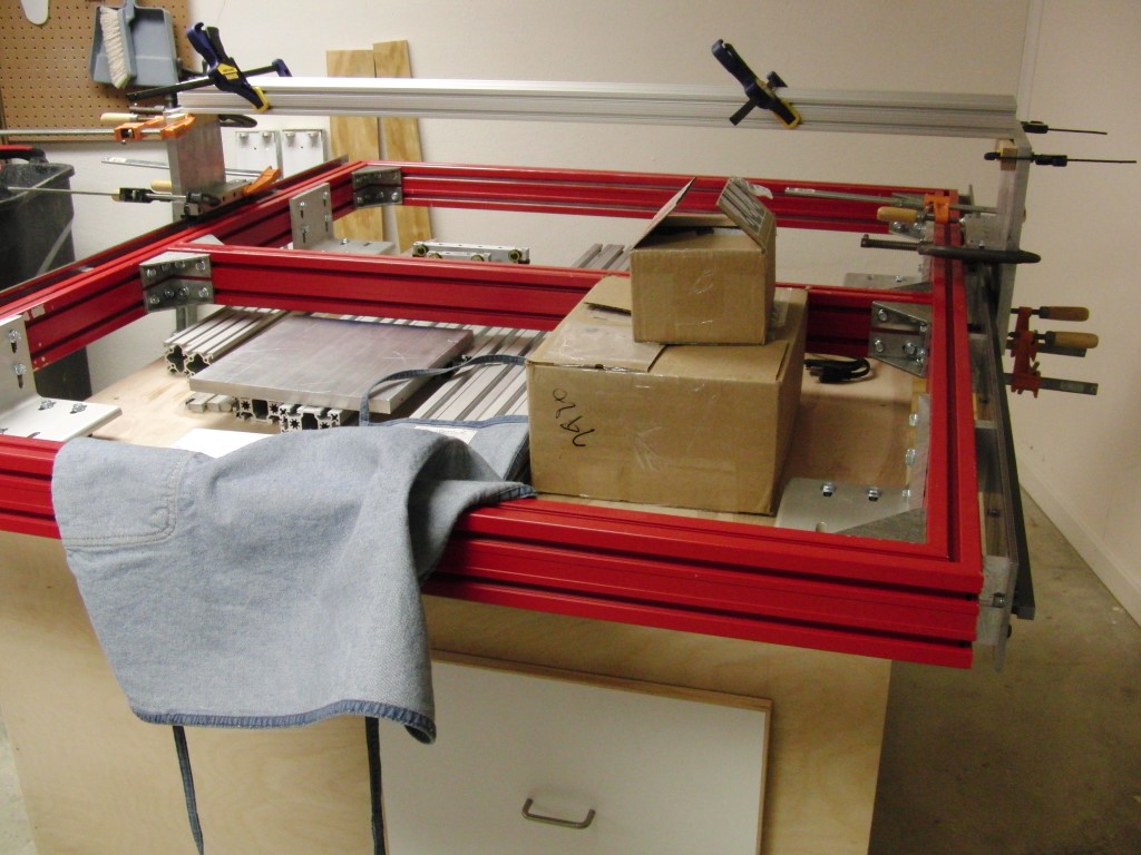
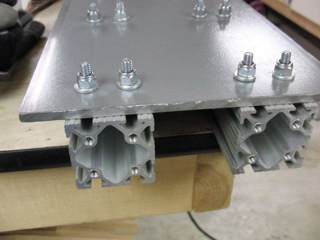
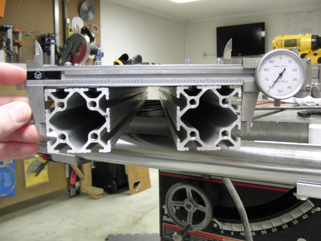
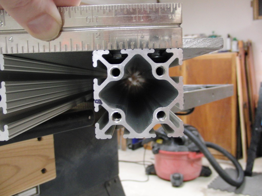
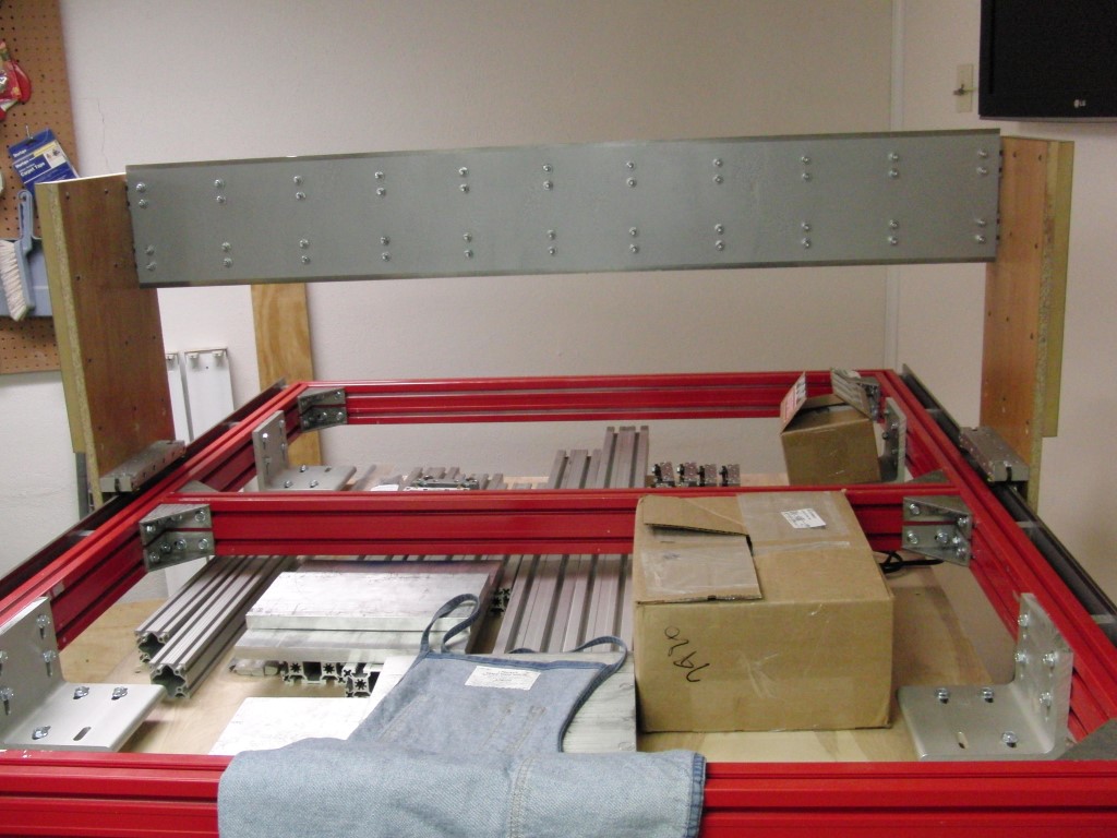
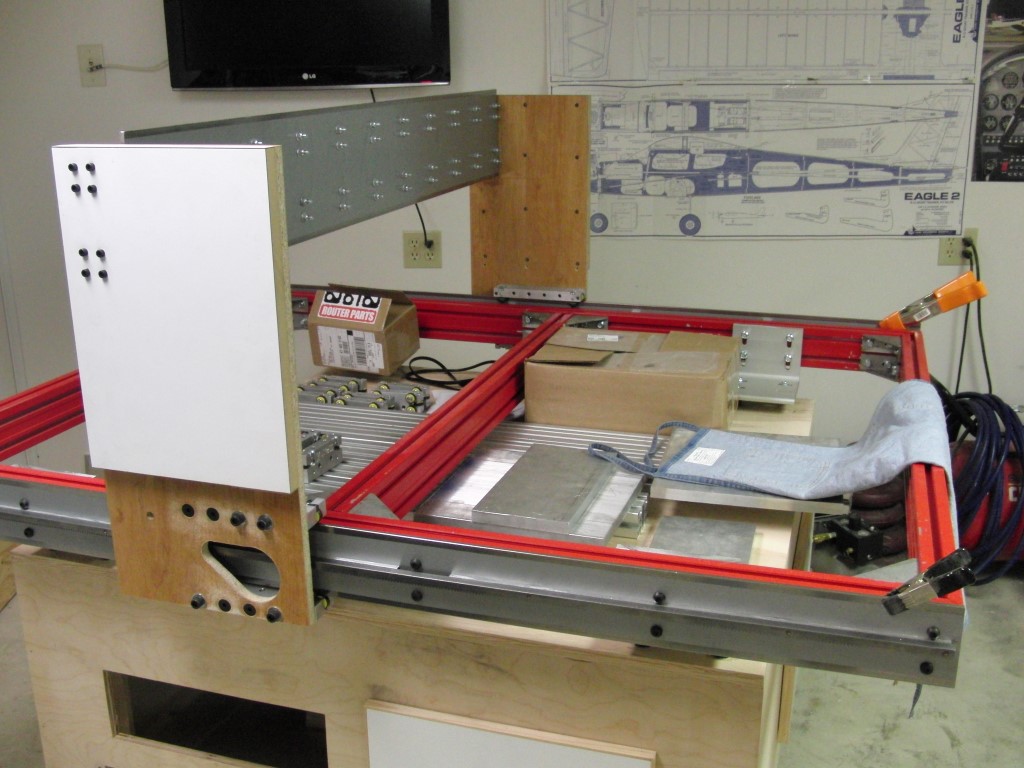
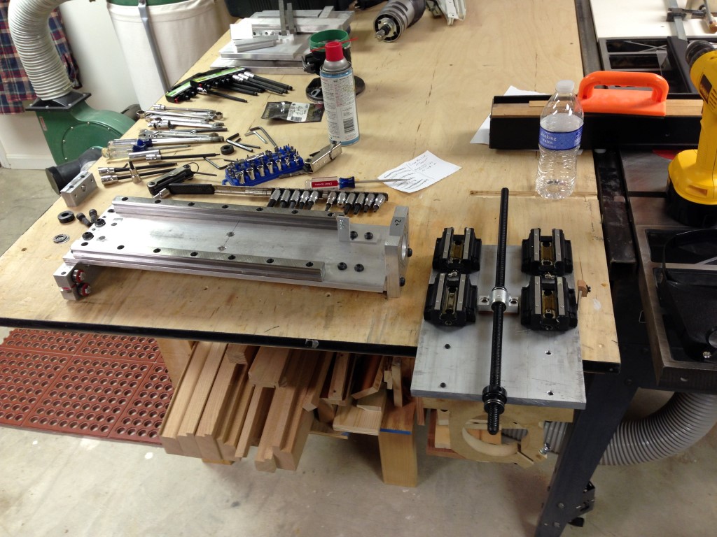
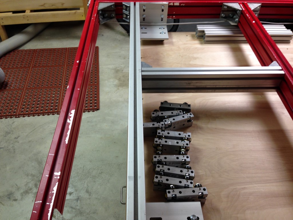
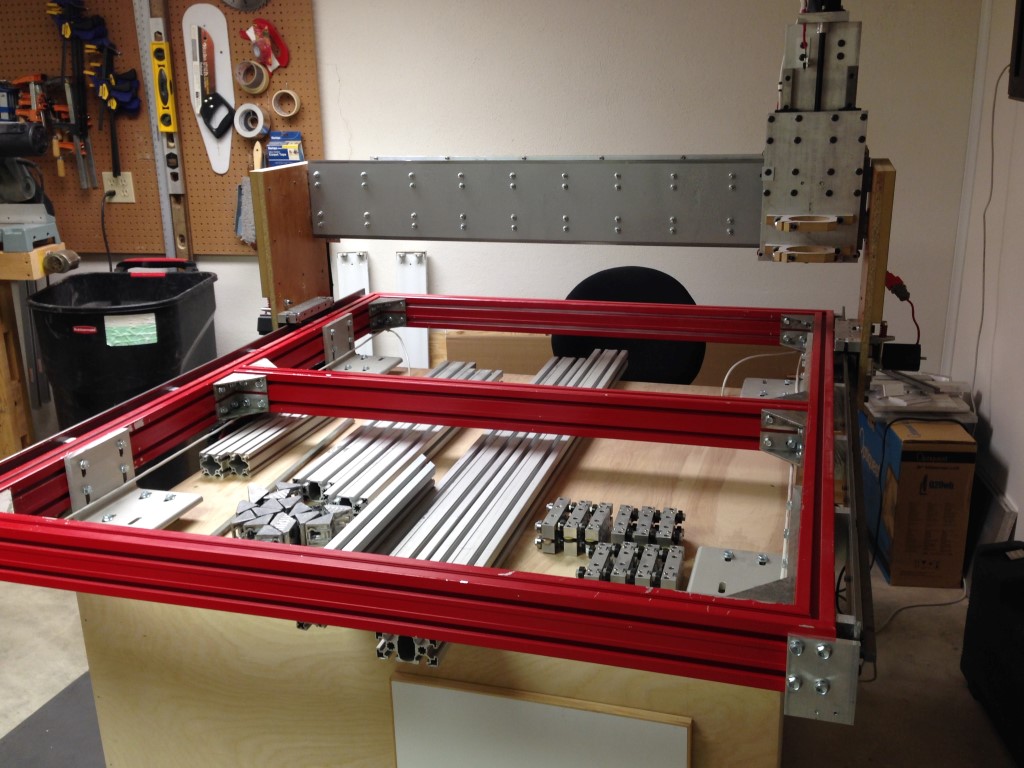
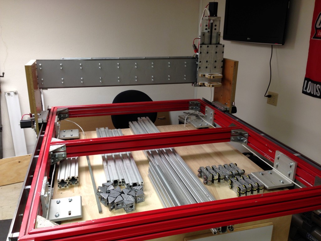
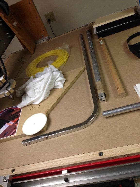
This is the starting pile of materials that I had accumulated, the Rexroth will be mitered at the corners and assembled with 90degree brackets that are bolted together.
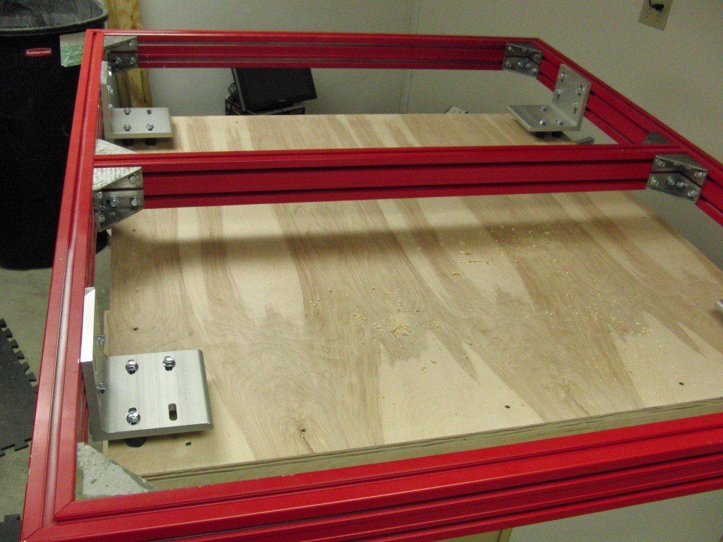
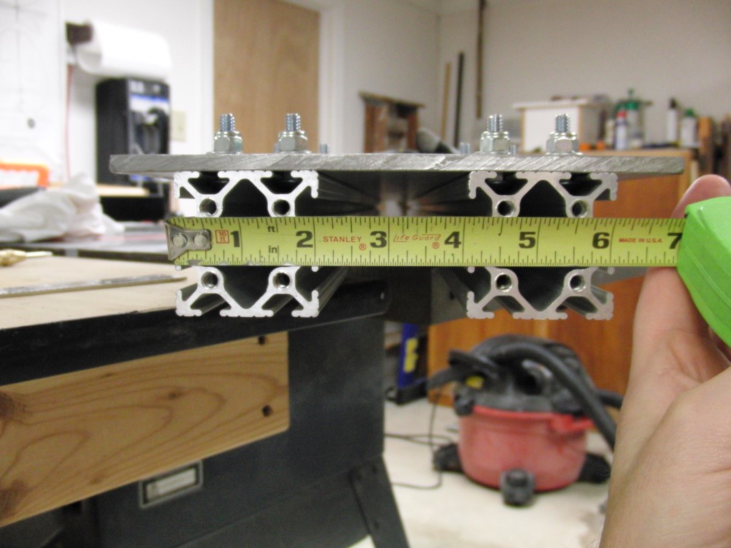
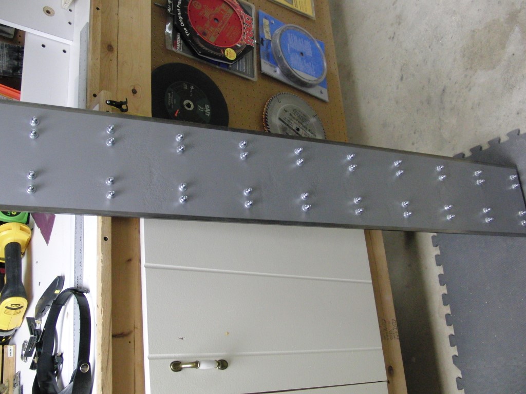
I also added another cross support on the frame to provide any additional stiffening I could, since I’m a beginner, I’m not sure what I’m up against.
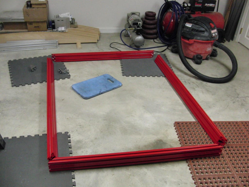
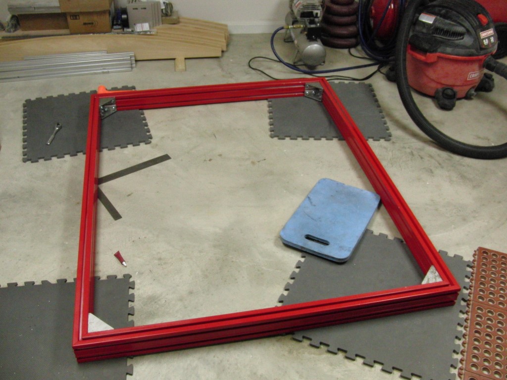
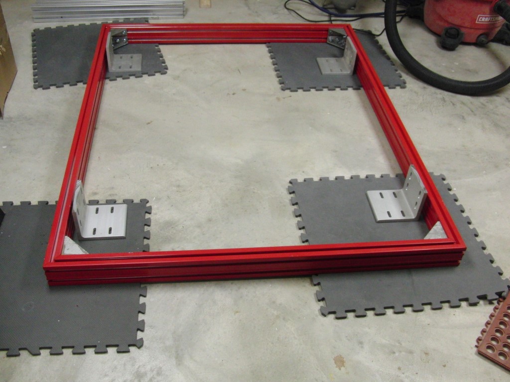
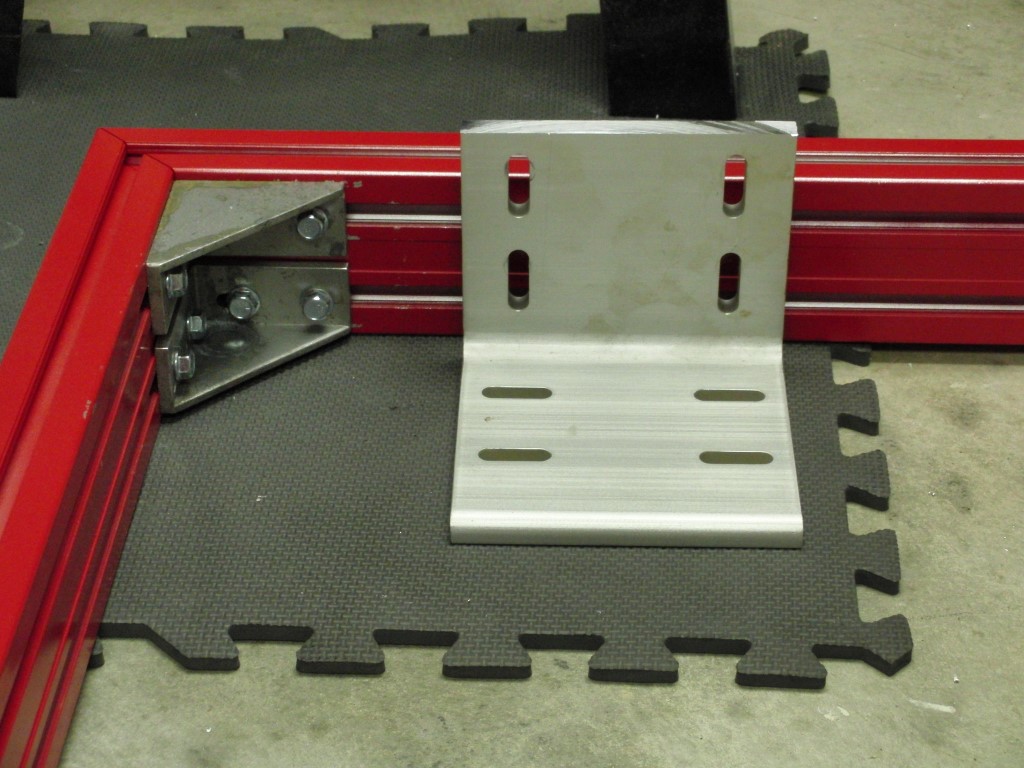
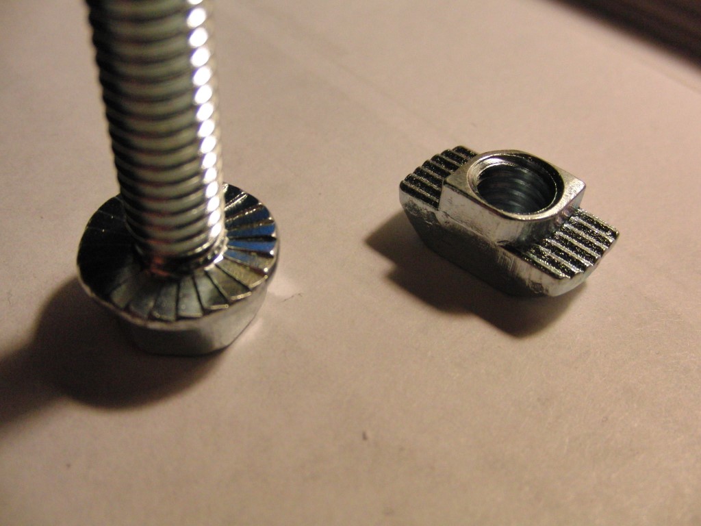
I’ve tried to eliminate the possibility of loosening by using serrated bolts, loctite and t-nuts, time will tell.
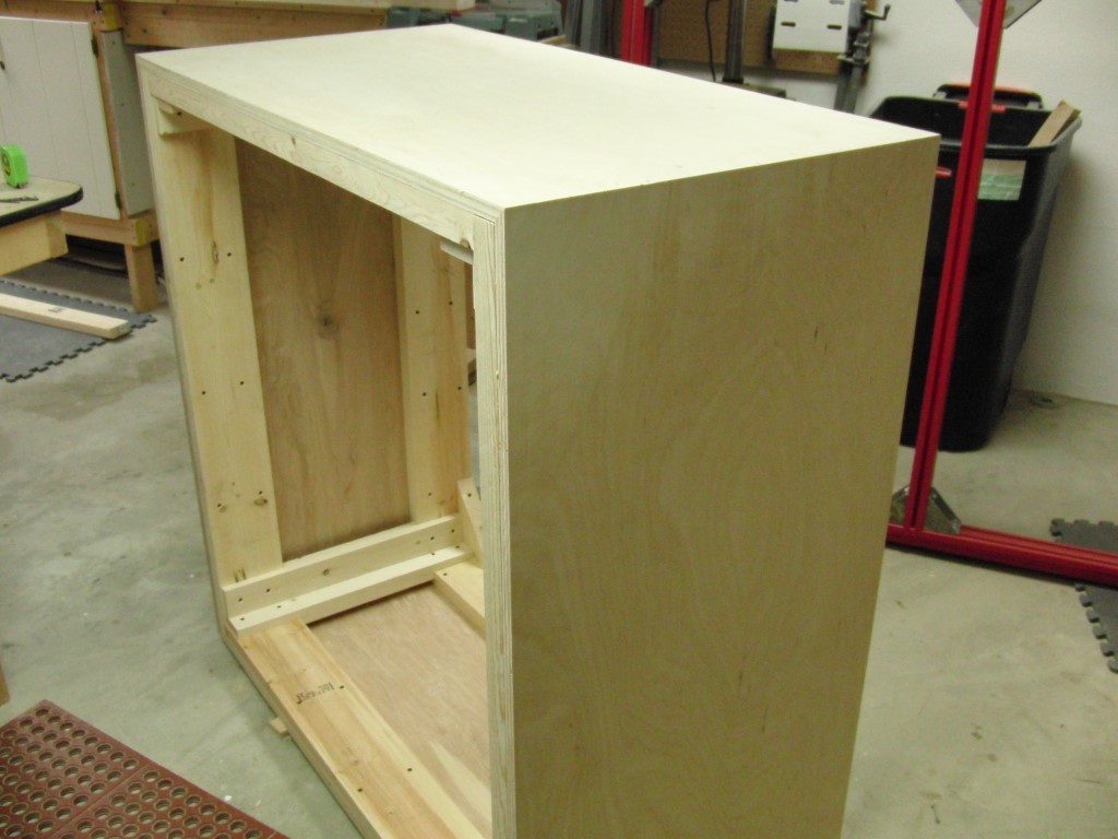
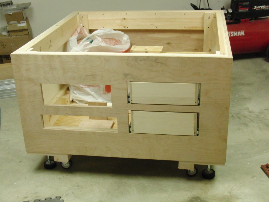
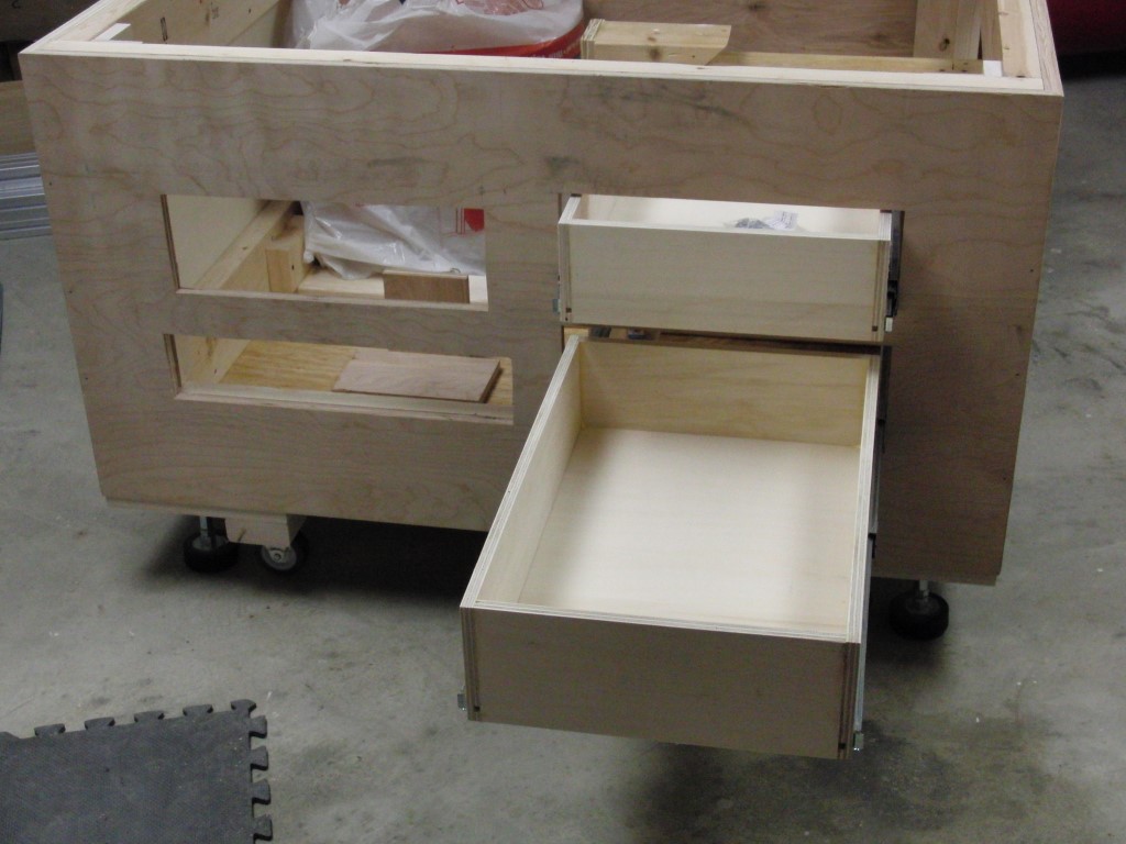
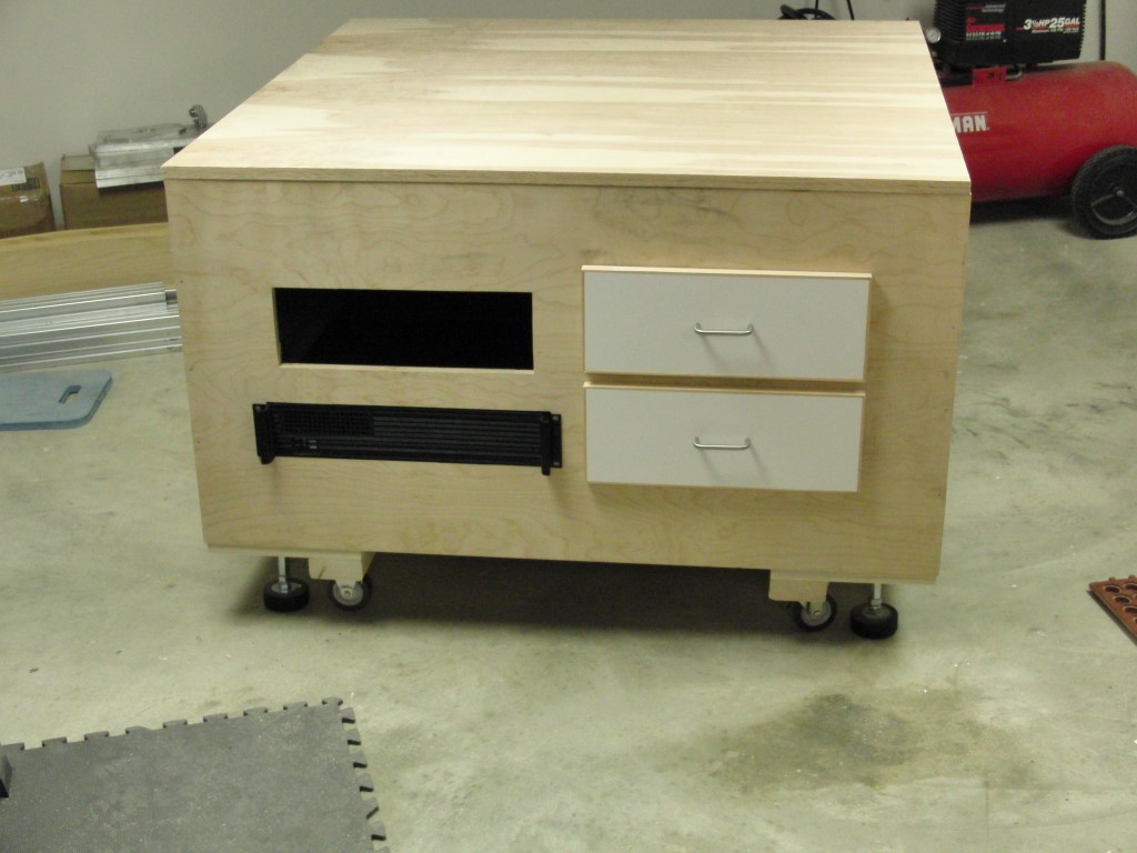
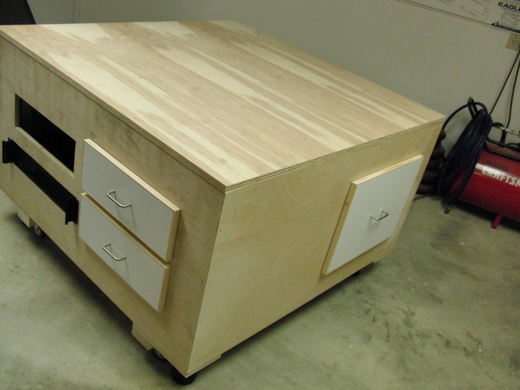
I decided to go with a cabinet for the base of the CNC and have been trying to get that finished for the past couple of weeks. Due to my busy work schedule and other commitments its been kind of difficult to squeeze in CNC time but never the less I was able to mostly get it done. the drawer will get cut before I put the top on it.
The cabinet will also house the electronics and I think some type of sound deadening material is in order, If the base weren’t so heavy I’d have my buddy spray some truck bed liner material in it.. insulation maybe??? any other thoughts on sound deadening material??
With the base about built hopefully I can get back to mounting frame and the CRS and the rest of the build.
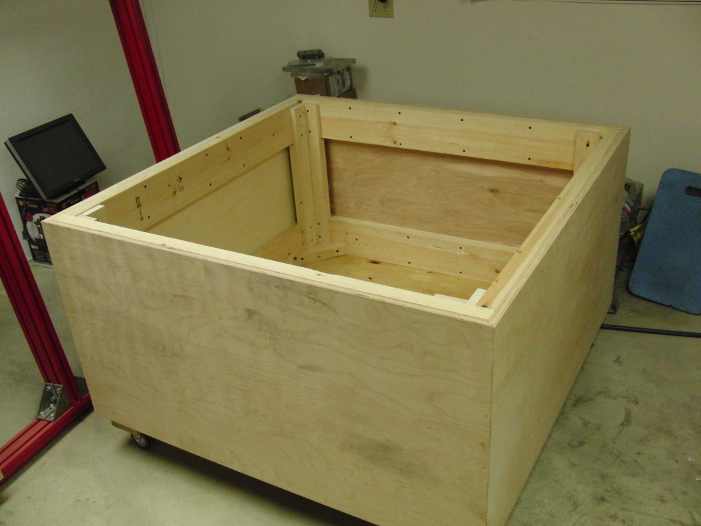
Originally I was thinking of making this totally moveable and on the casters I purchased from Harbor Freight but since my floor is less than level (go figure) I’ve re-thought the idea and I’m now going to go with Ger21’s suggestion of the Hockey puck adjuster levelers.. a use for one of my favorite sports paraphernalia.
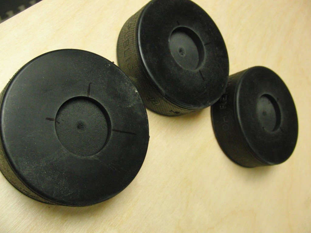
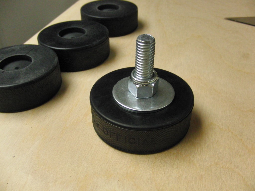
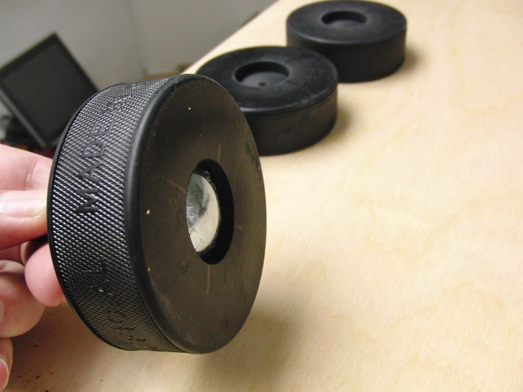
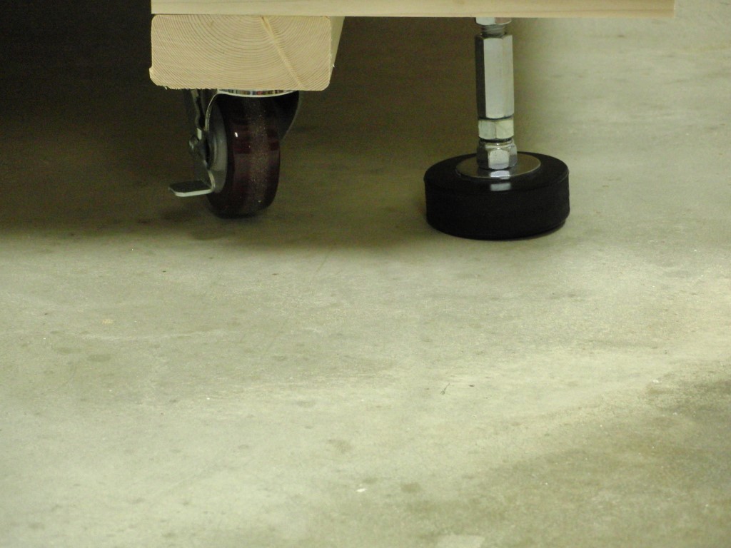
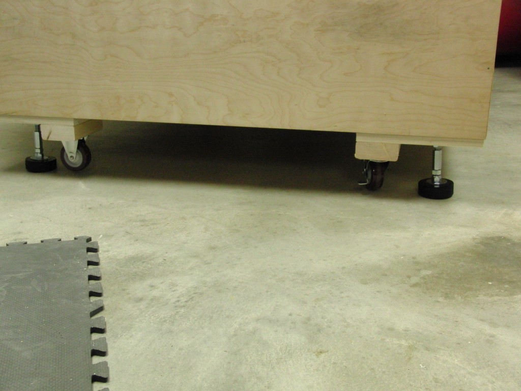
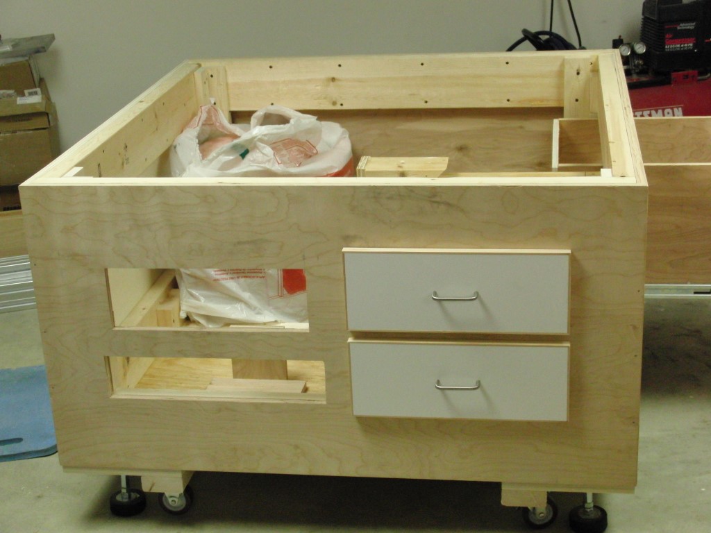
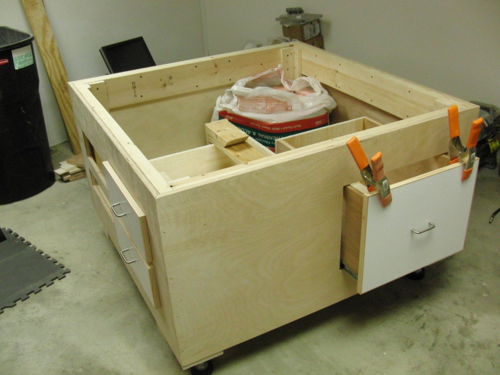
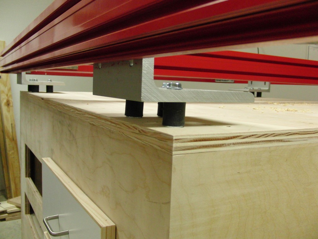
The base cabinet has been built with some drawers for some extra storage. The leveling feet made from hockey pucks is also done, they work well enough and were inexpensive so I can’t complain.
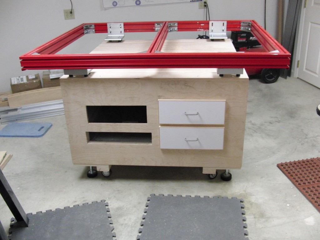
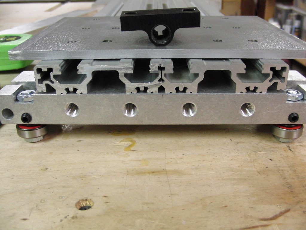
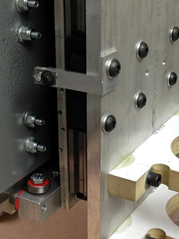
I’ve also installed some isolation dampers between the frame and base to help with vibration, well see if they help.
Time to get moving on mounting the rails and the gantry… with the Holiday’s here hopefully I should have a little more time to work on it.
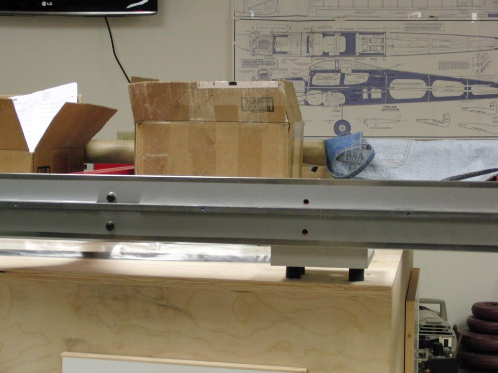
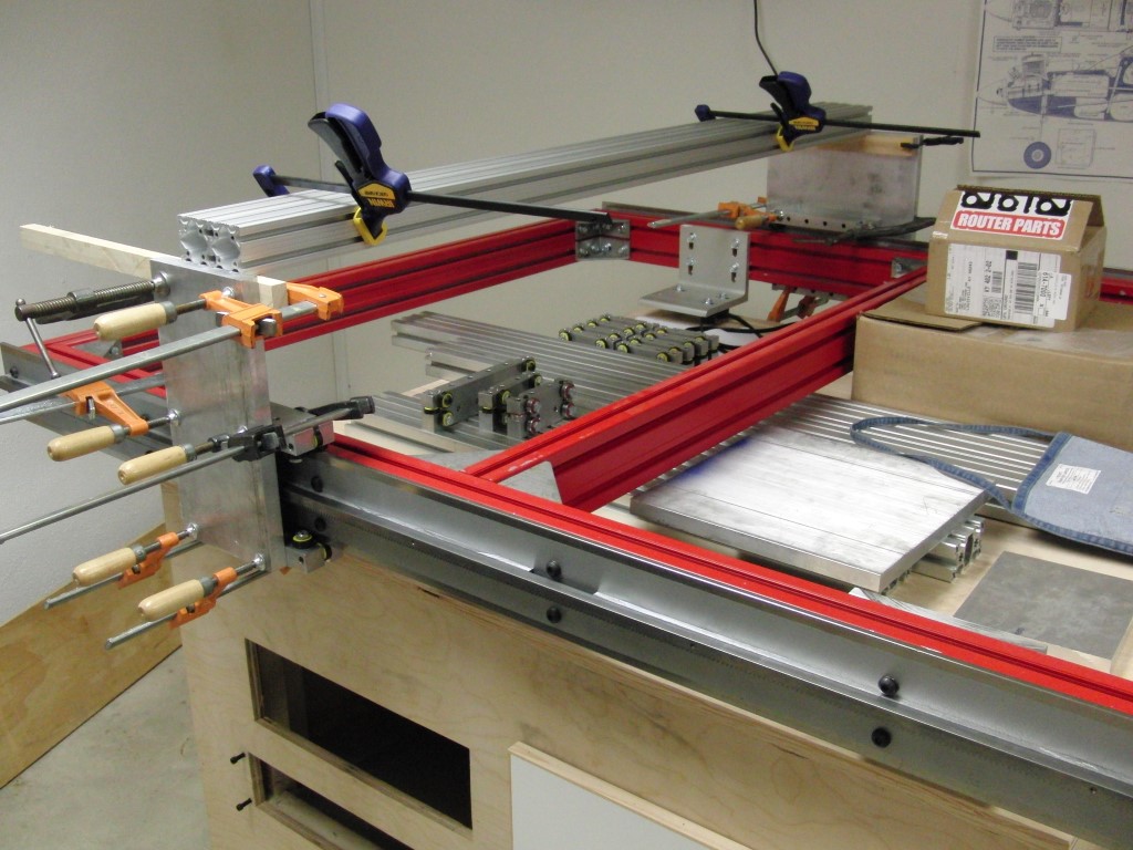
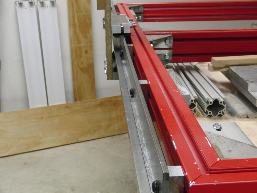
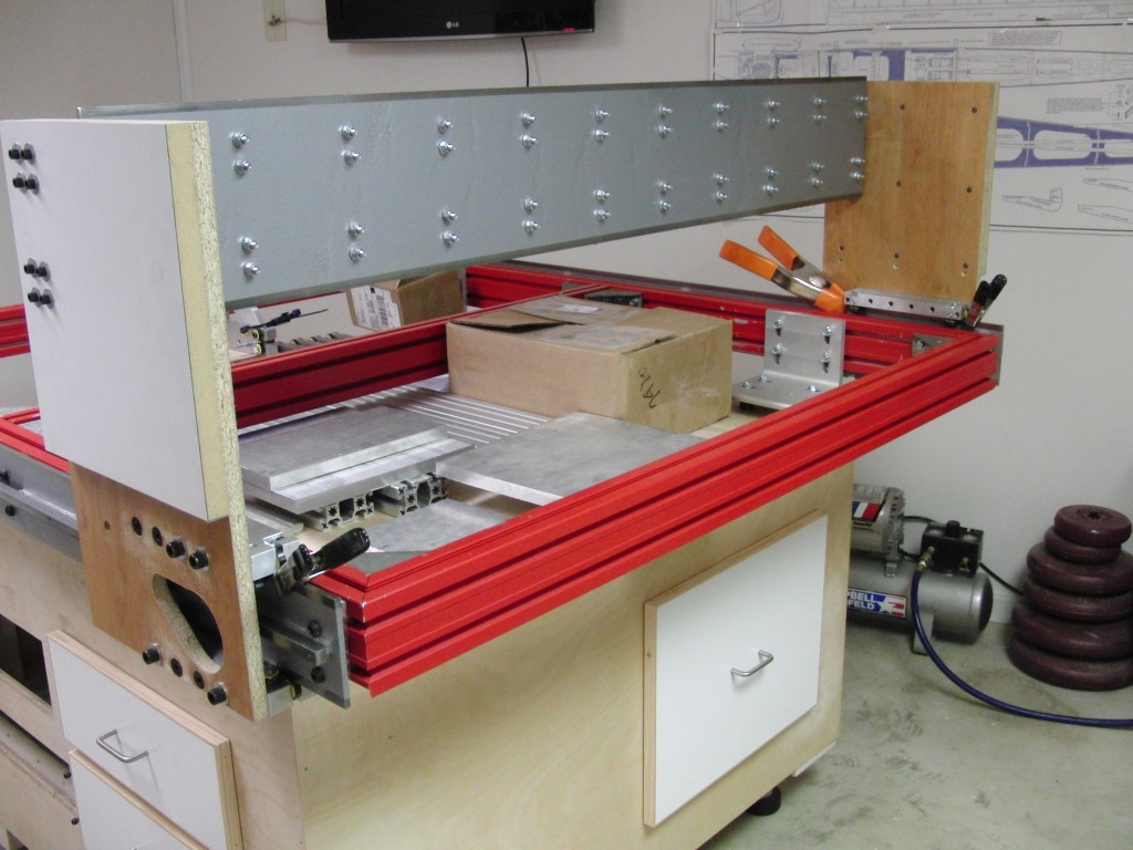
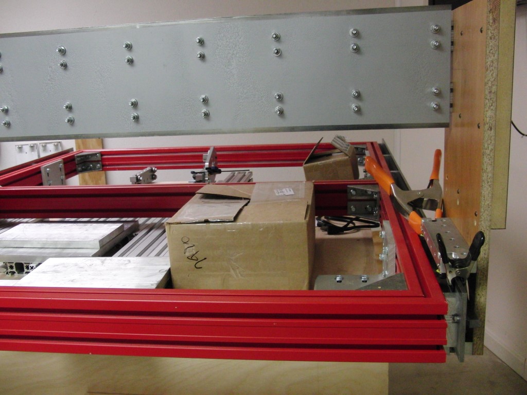
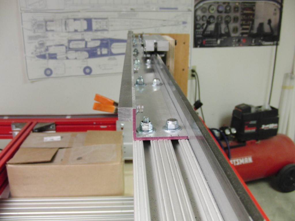
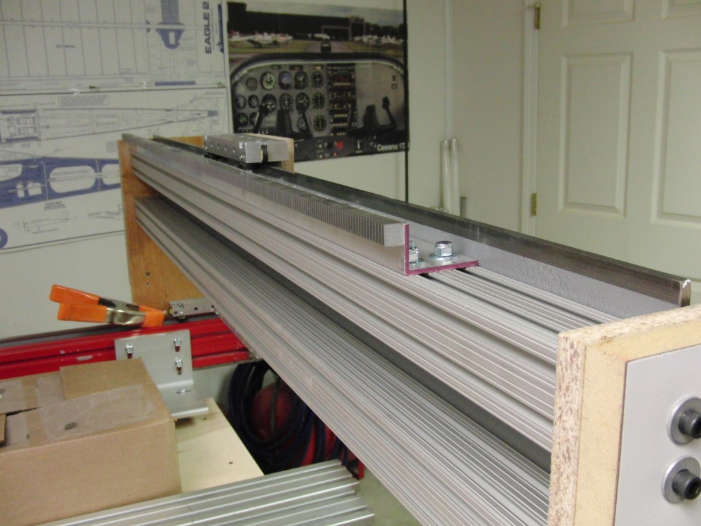
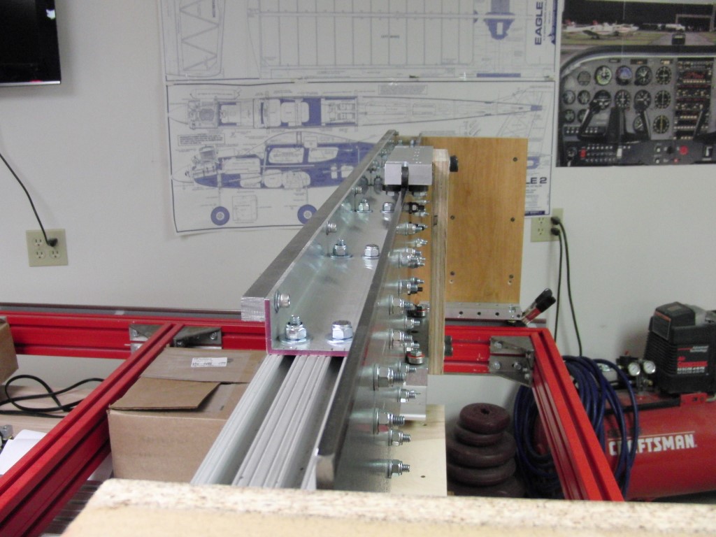
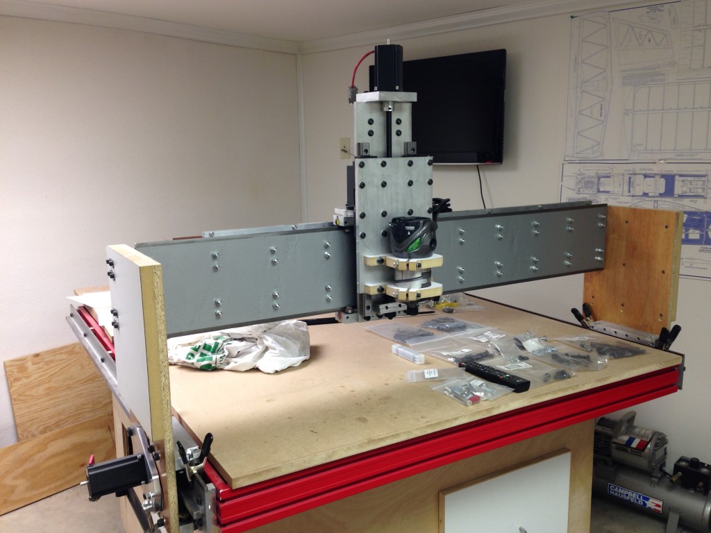
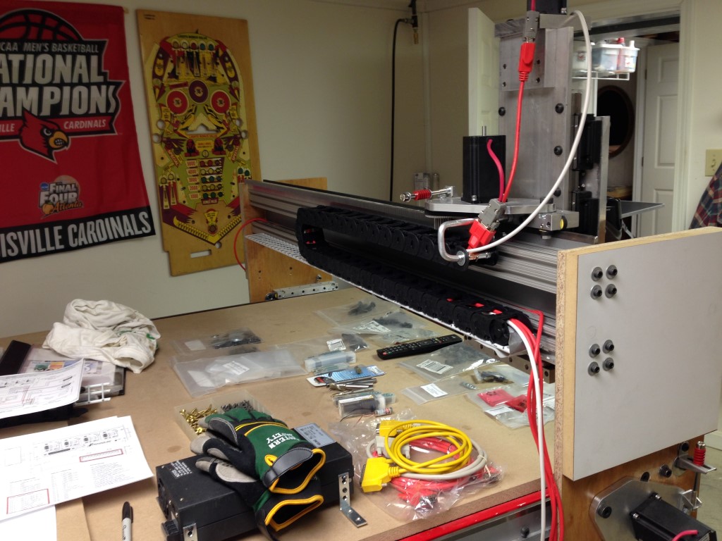
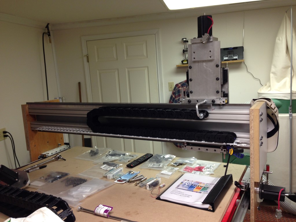
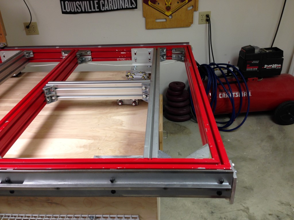
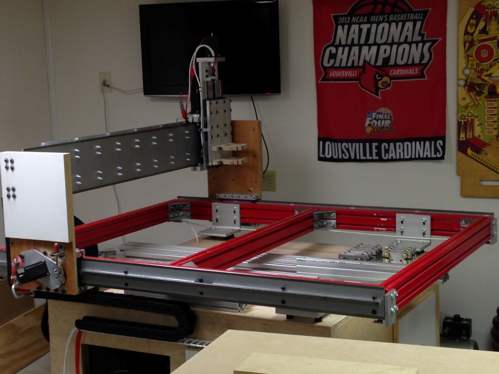
Here are a few more pics of the progress over the holiday weekend. I made some good progress even with limited shop time, drilling holes takes time…
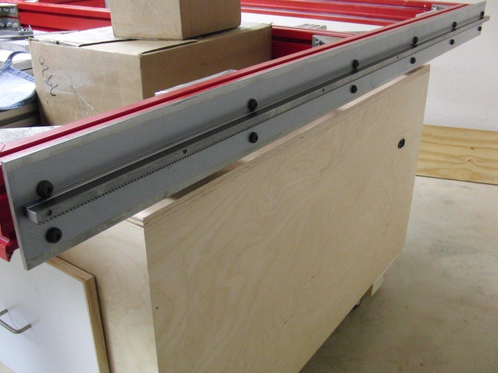
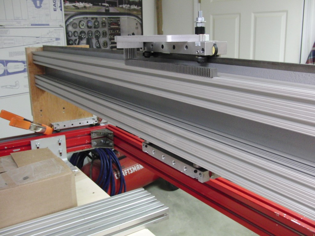
As you can see the rails are mounted and I have at least one gantry side in the works, still waiting on some metal.
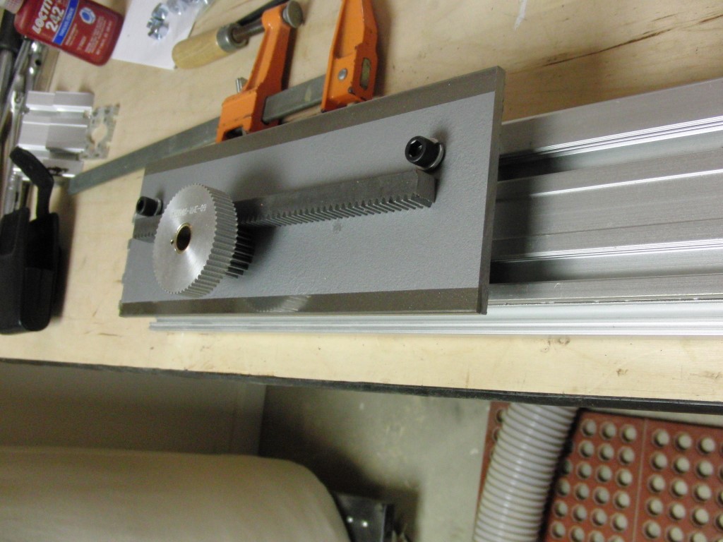
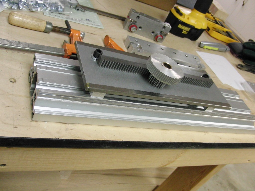
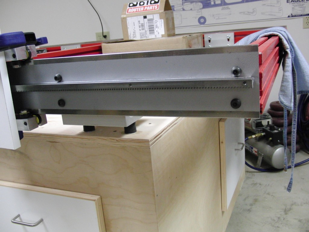
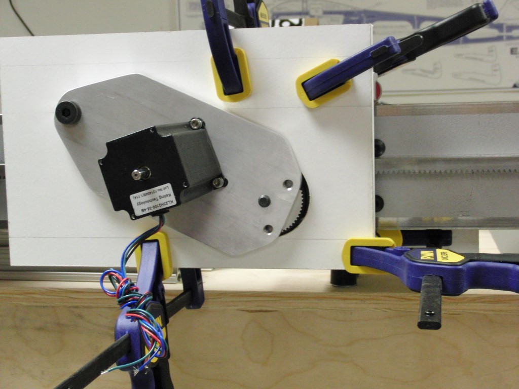
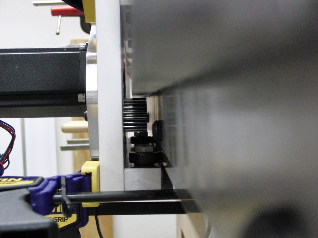
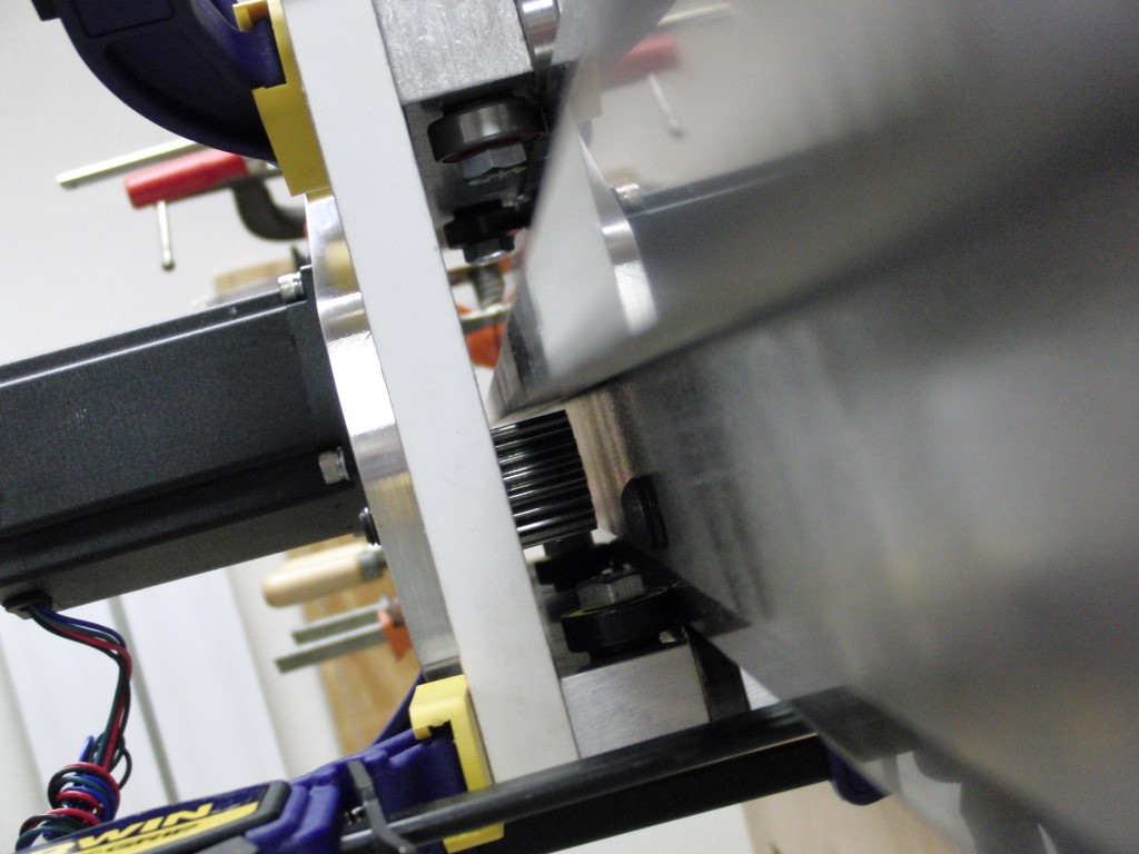
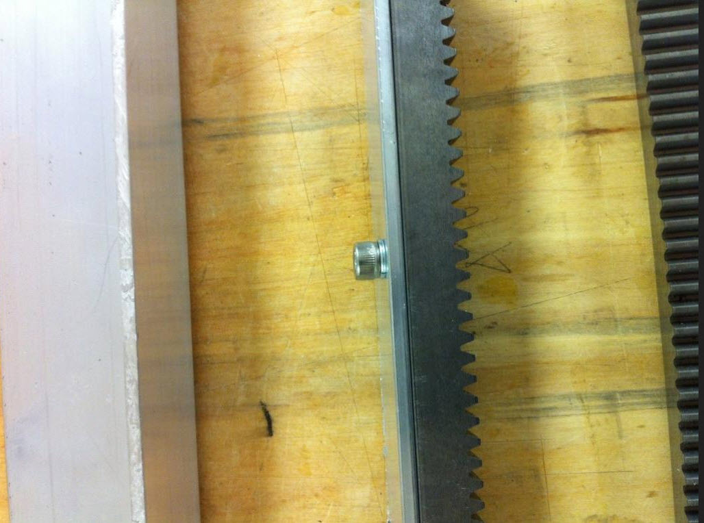
I spaced off the gear rack as opposed to flush mounting it to the steel rail to get a more solid mesh between the pinion teeth and the rack. Since this build is not from a design I have to take what I get and work with it..
Making some good progress just need to find some more time… money wouldn’t hurt either.
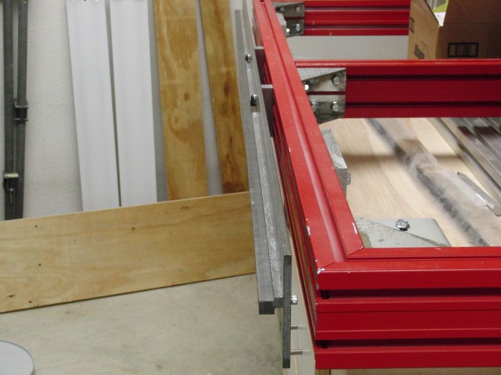
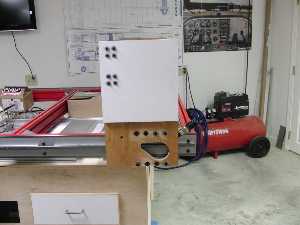
One of the first steps was to try and determine the width of the gantry so I mocked up some gantry sides and attached them to the sides of the table and took some measurements.
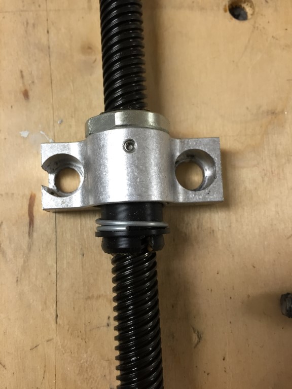
I’m planning on using an ACME screw for the Z axis but I think its going to need something to offset the weight otherwise I would anticipate the ACME backlash nut is going to wear quickly…
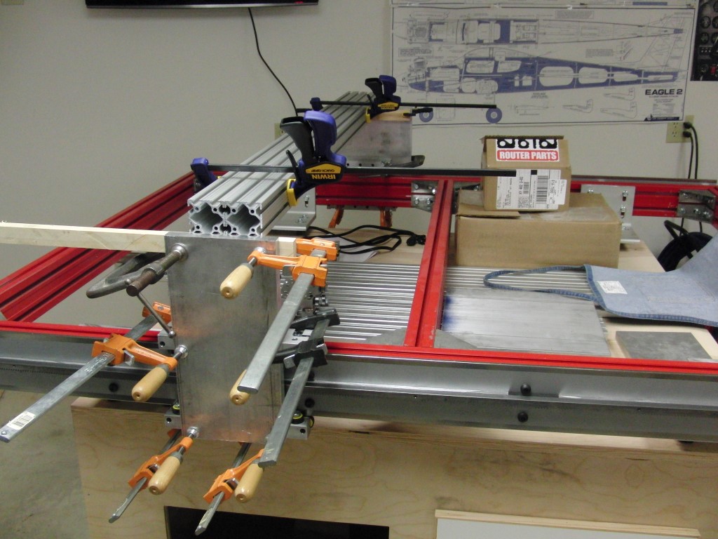
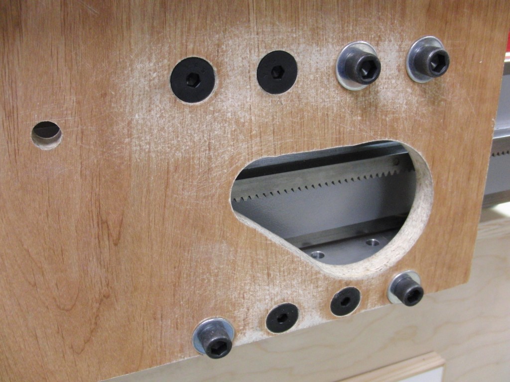
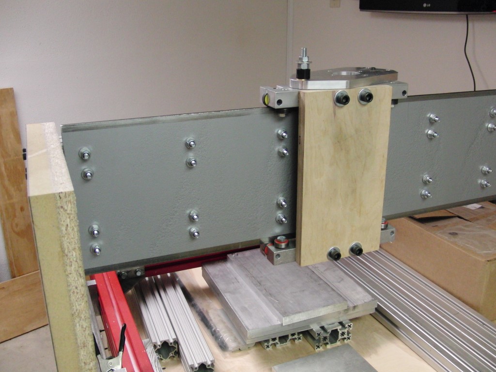
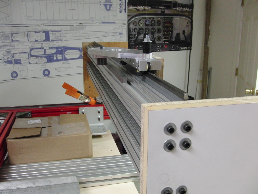
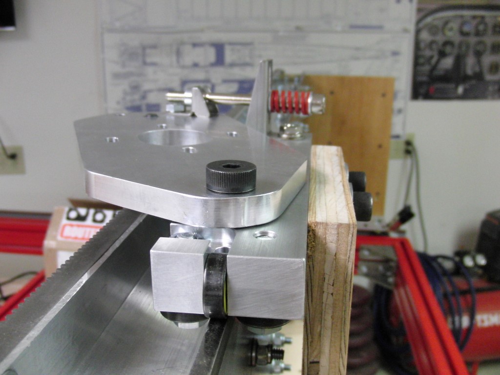
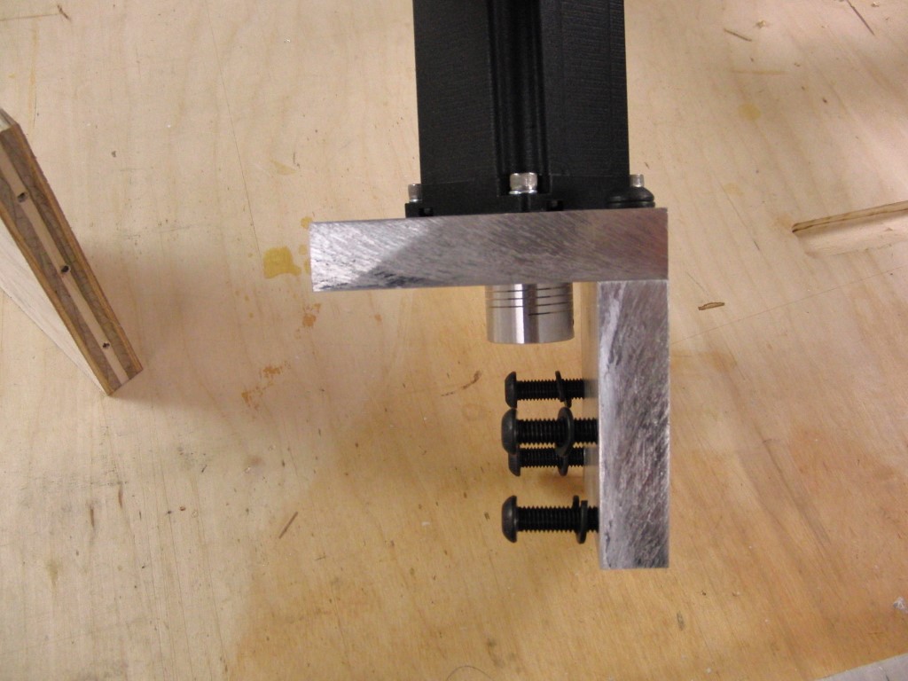
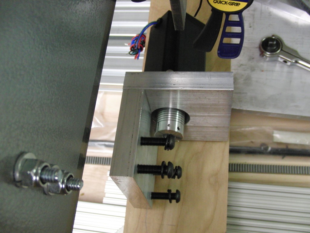
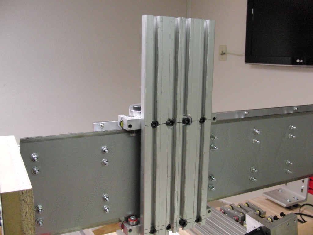
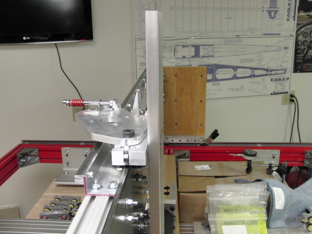
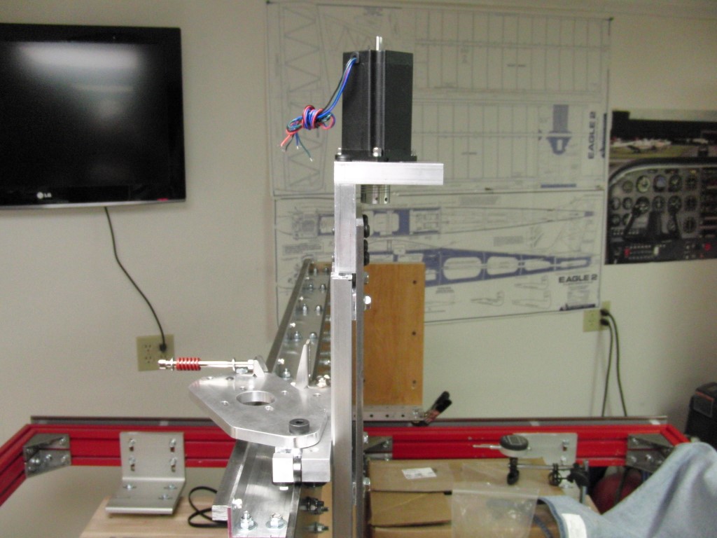
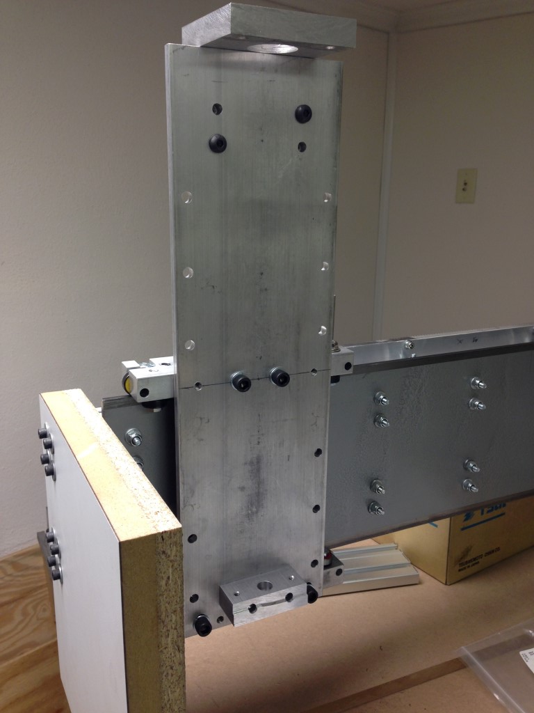
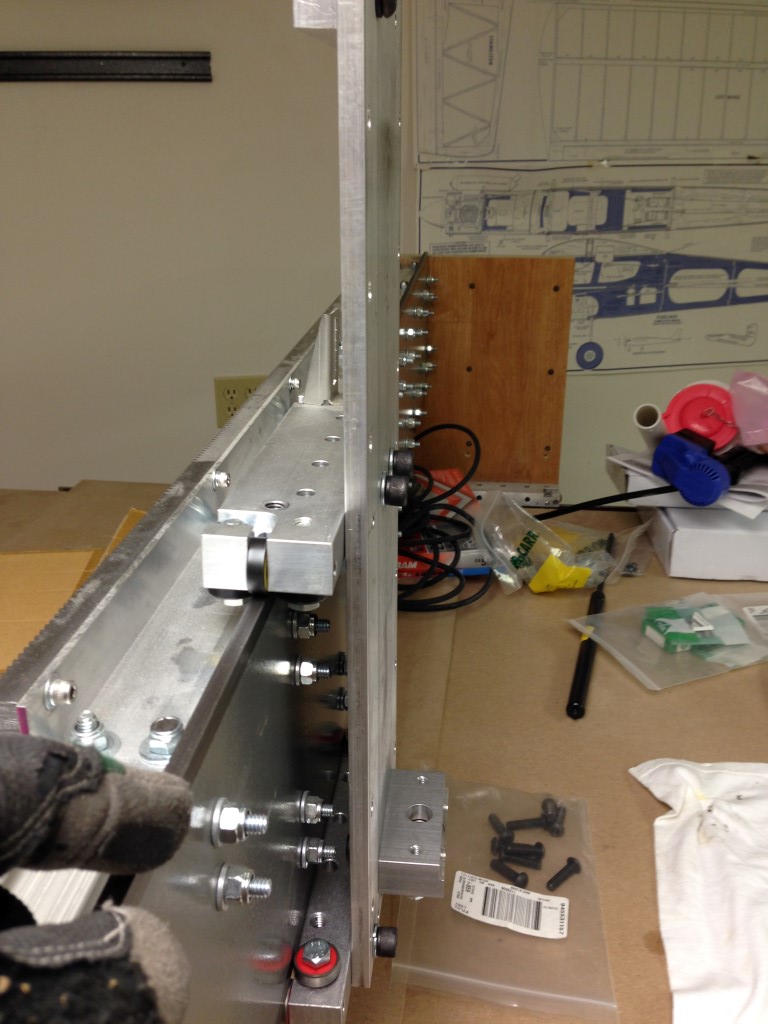
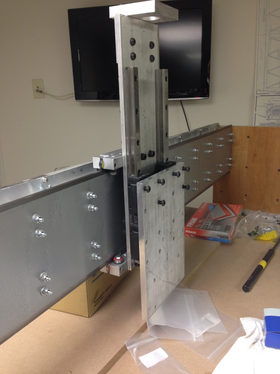
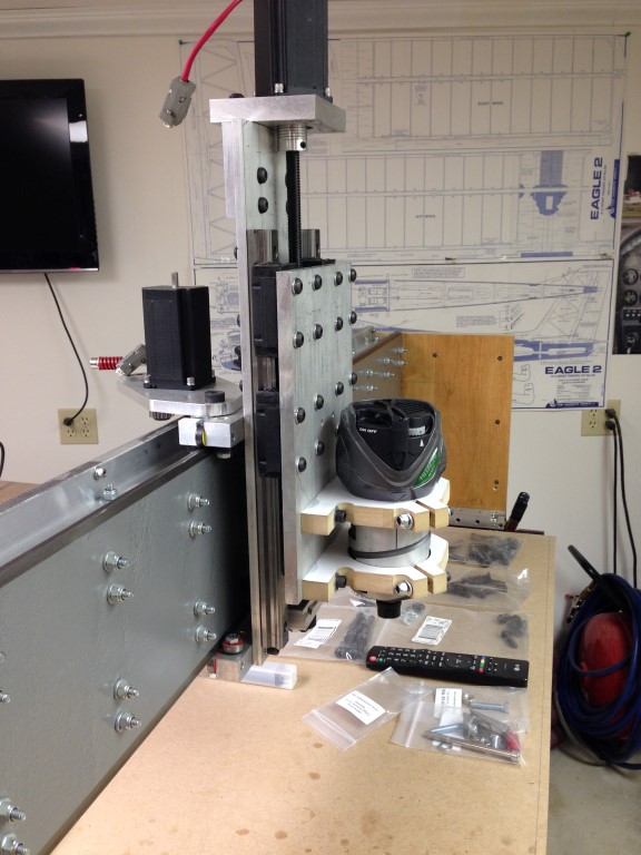
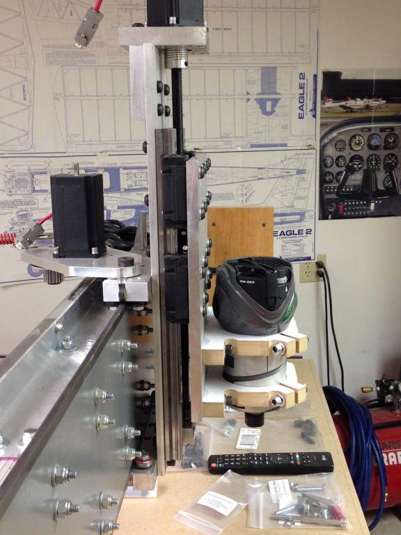
Here are few more progress pics… lots of holes to tap in the gantry Z axis plate. Some might notice the differences in the heights of the gantry sides originally it was 12″ now its 8″, I’m much more comfortable with 8″. I’ll mill the sides out of aluminum once I know I have a working design.
The important items to notice is the need to make sure the rack and pinon motors work as designed and they have clearance, etc. So, lots of fitting and adjusting here, once this is set its hard to turn back.

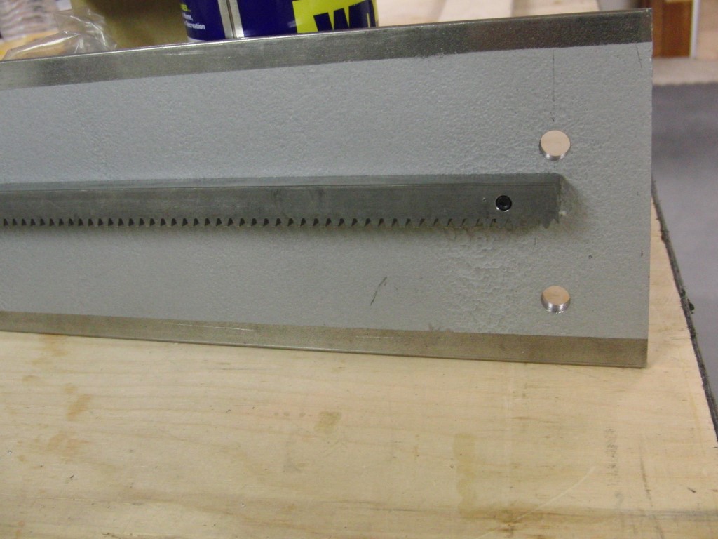
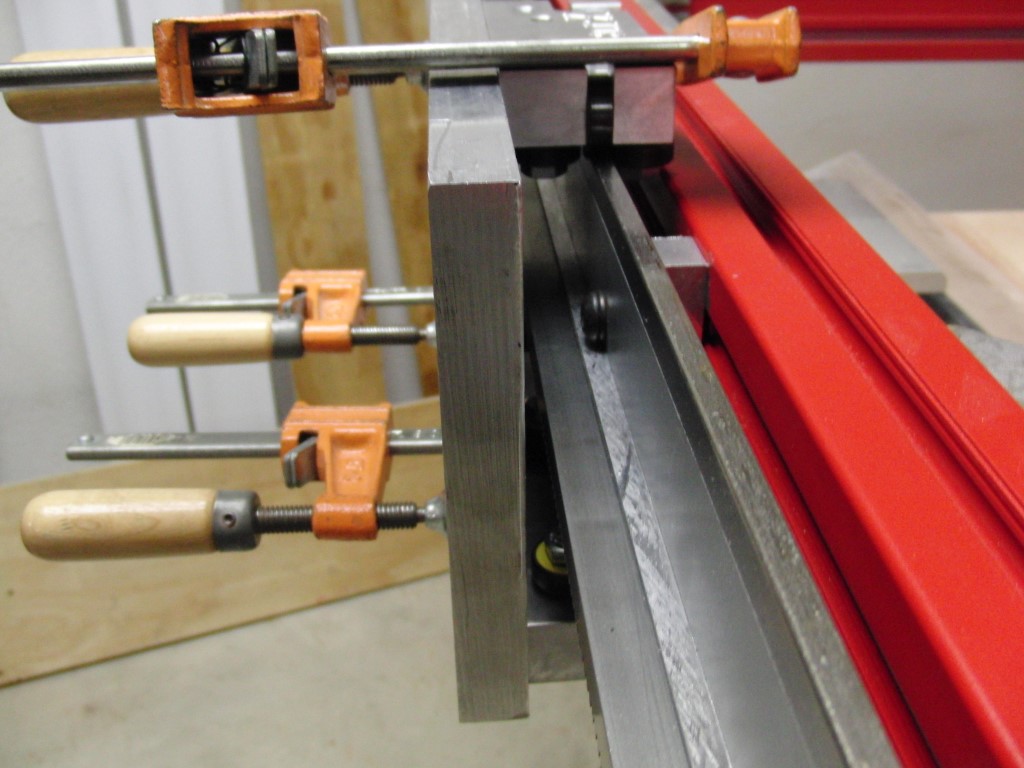
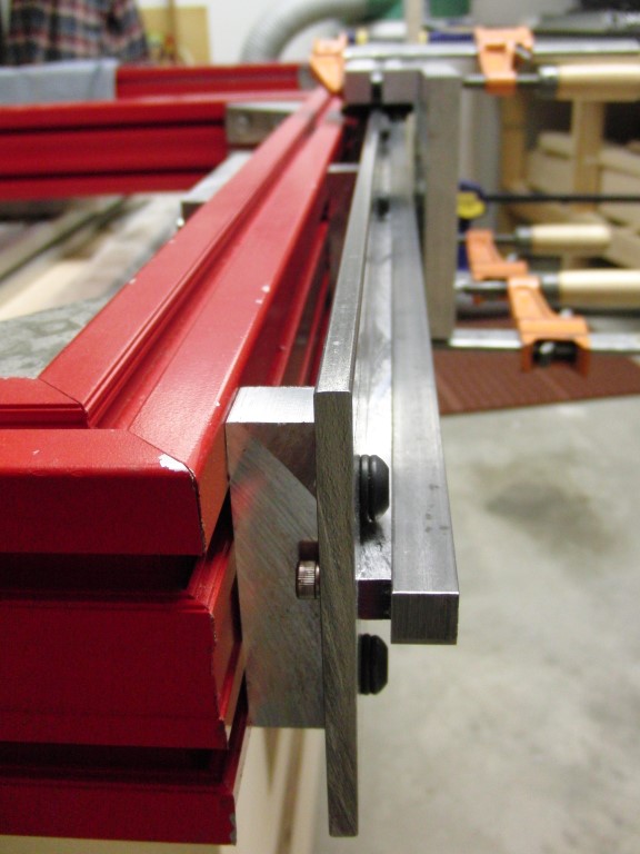
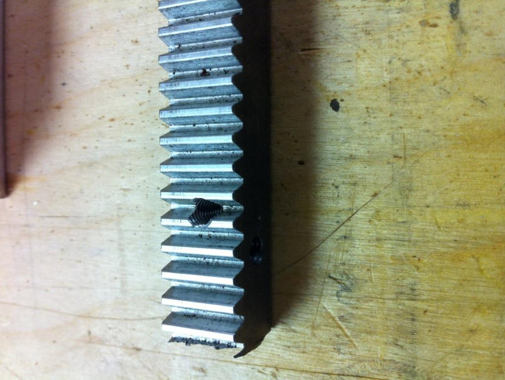
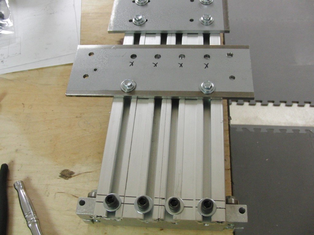
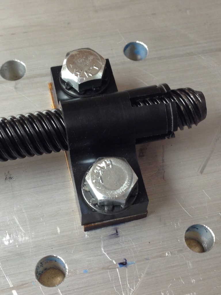
On another front… my initial thought was to drill through the rack but I later decided to just bottom tap the holes to prevent any unecessary wear on the pinion gears.
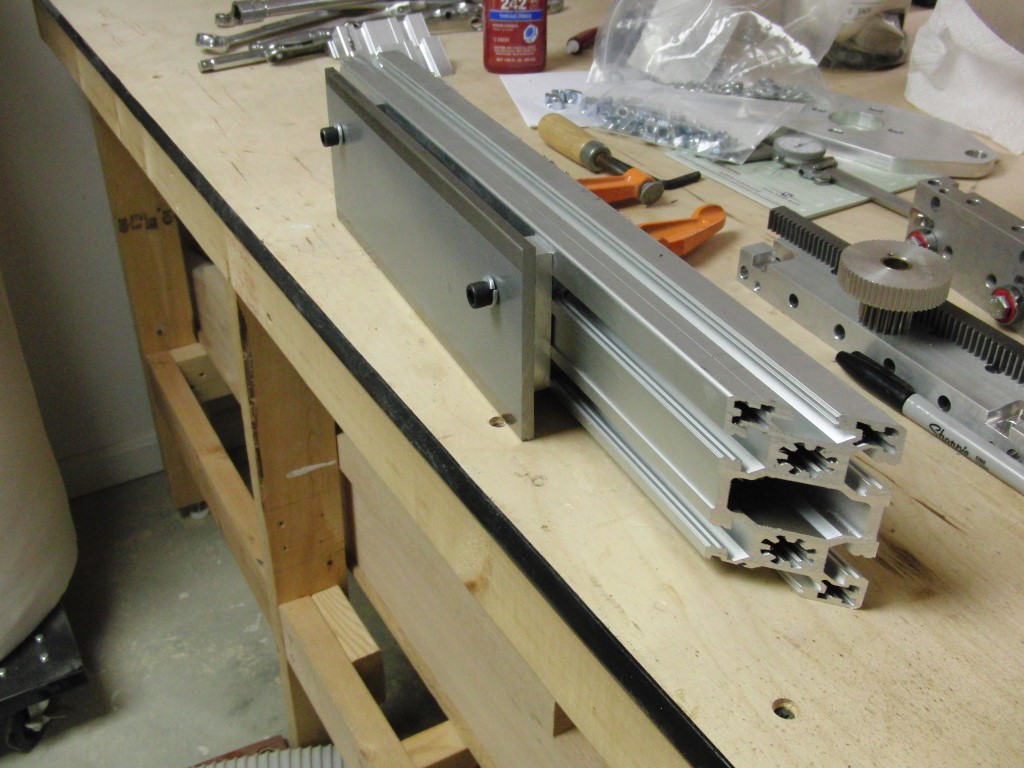
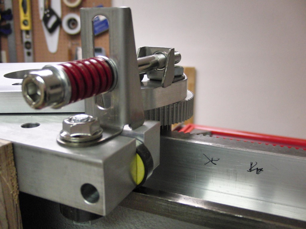
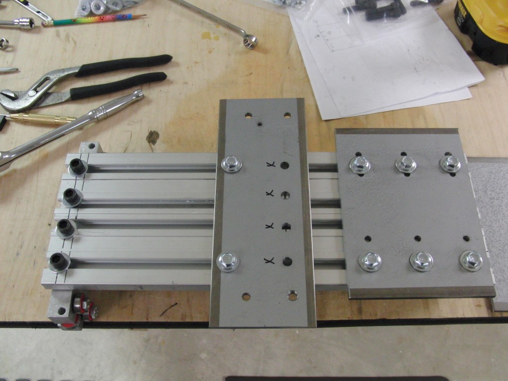
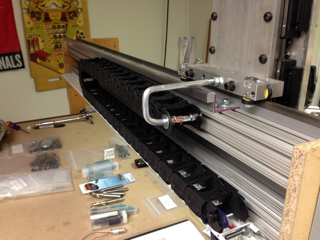
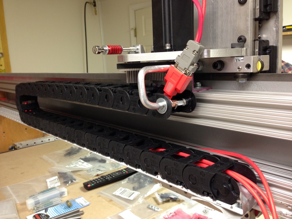
I Finished the Y axis and rack mount today. I had to mock up a bracket for it since I couldn’t directly mount the rack to the extruded aluminum.
I really like Ahren’s (CNCRouterParts.com) new tension adjustment kit, well thought out and made.
Moving onto the Z once I finalize the design, I’d like something compact but with enough movement to accommodate the 8″ travel.
Shouldn’t be much more metal fabrication after the Z, the rest should go smooth and quick. I’m getting antsy to fire this thing up…
I ordered some 8″ CRS for the Z axis and I’m now thinking this may turn out to be too heavy after bolting on the plate for the router and mount and what not…
I’m not to keen on the 8″ width but it will add stability but it will also add weight.. if it holds up well I’ll end up reworking it in the long run.
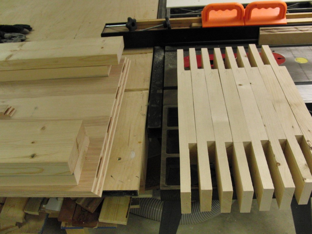
Since the steel had some flex and I didn’t think it was stable enough lengthwise I backed it with some RexRoth that I ripped on the table saw – what a mess swarf makes. Who named it swarf anyway it should be called “instant shop mess”!
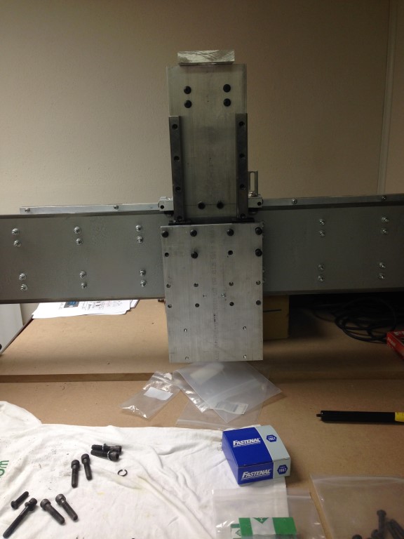
I jigged up some steel so that could drill the pieces for the linear bearings. Since I don’t own any true machining equipment I had to go with the drill press to counter sink a couple of the holes, not optimal but got the job done until I can rework the Z axis.
I sure hope this all comes together in the end.. it sure is looking good.
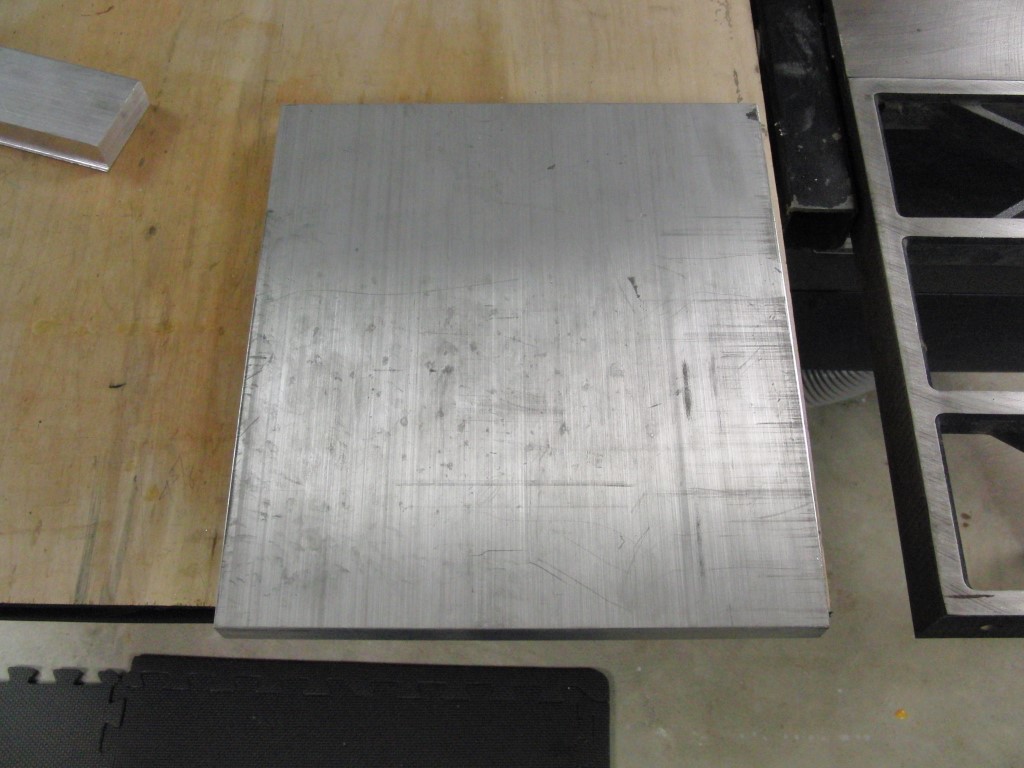
The Z is HEAVY!, I think my Z will weigh in around 23lbs…
10 x 11 x .75 = 82.50 X .283 = 23.35 ouch!
It makes me want to think about some type of counter weight to offset the 3/4 plate not to mention the additional weight of the router.. I think the ACME nut is just going to prematurely wear and develop backlash or quite frankly fail.
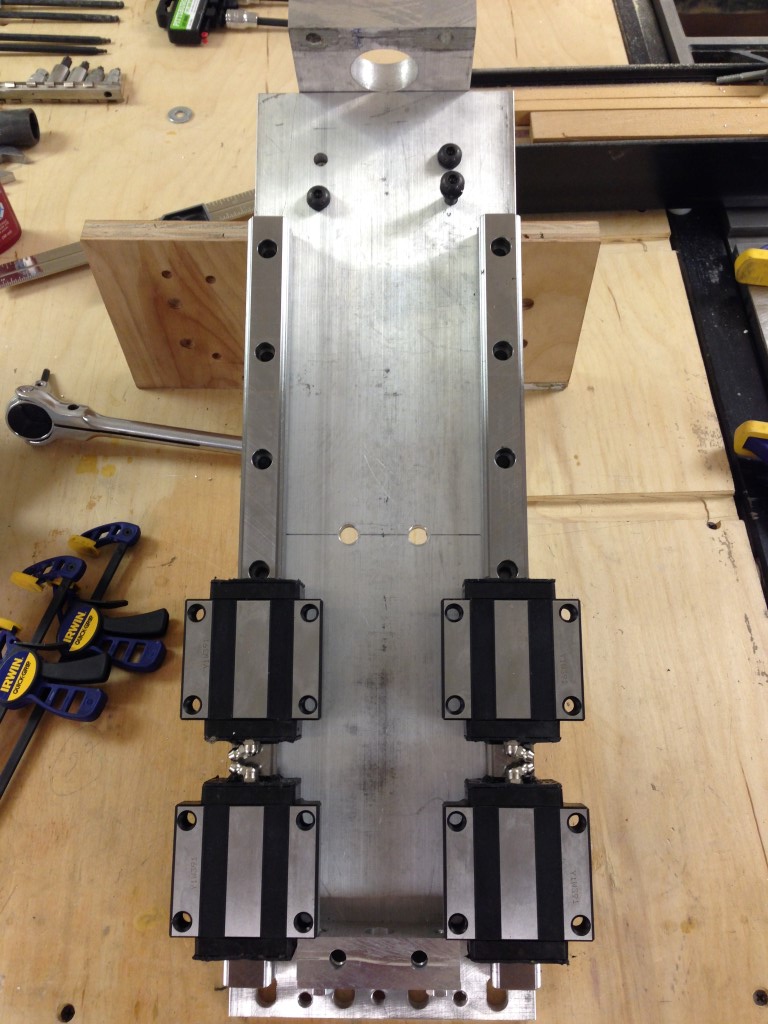
So I was thinking about going with a linear slides for the Z-axis and scrap my current design. My initial thought is a 20mm unit with 2 pillow blocks per rail and an approximate length of about 20″.
As luck would have it I landed on some THK HSR 25’s and 400 mm length rails from E-Bay, I think they will do the job nicely.. so off to rebuild the ZAxis I go, stay tuned…
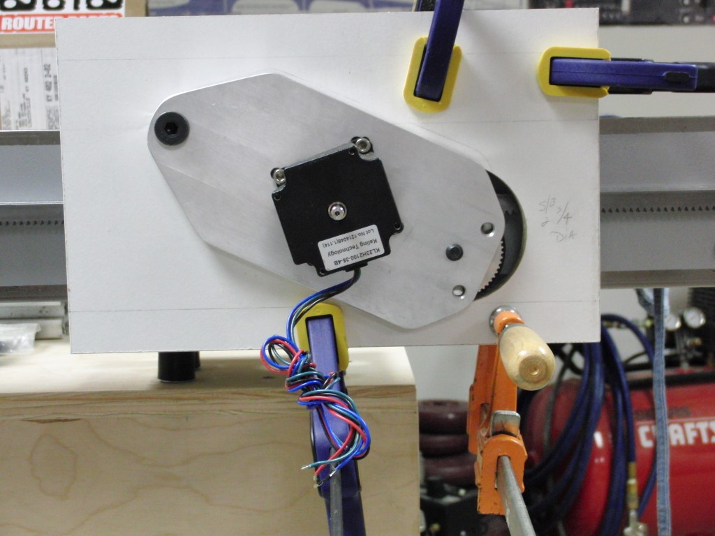
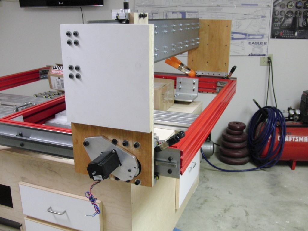
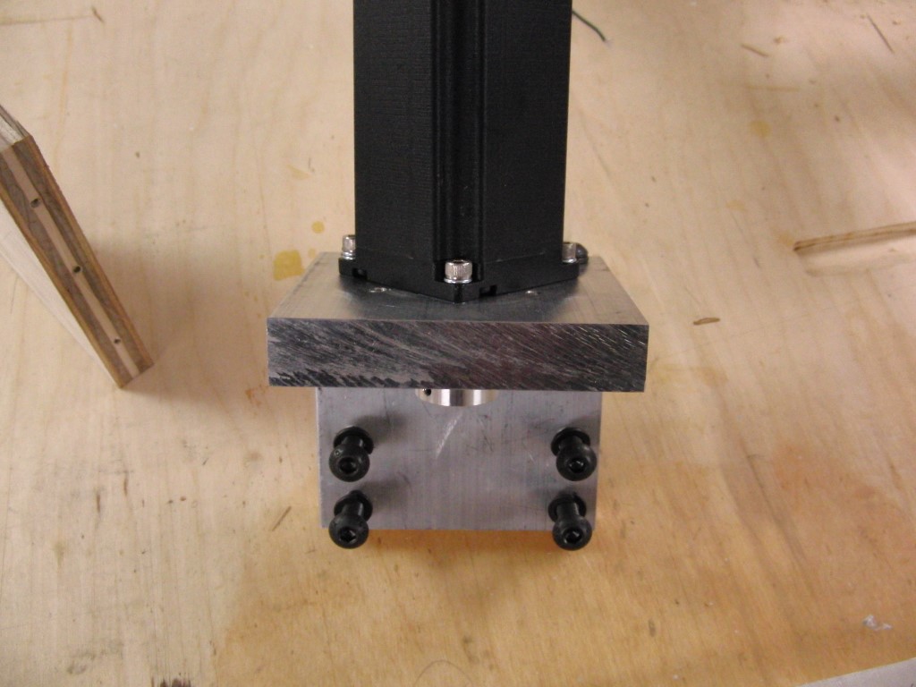
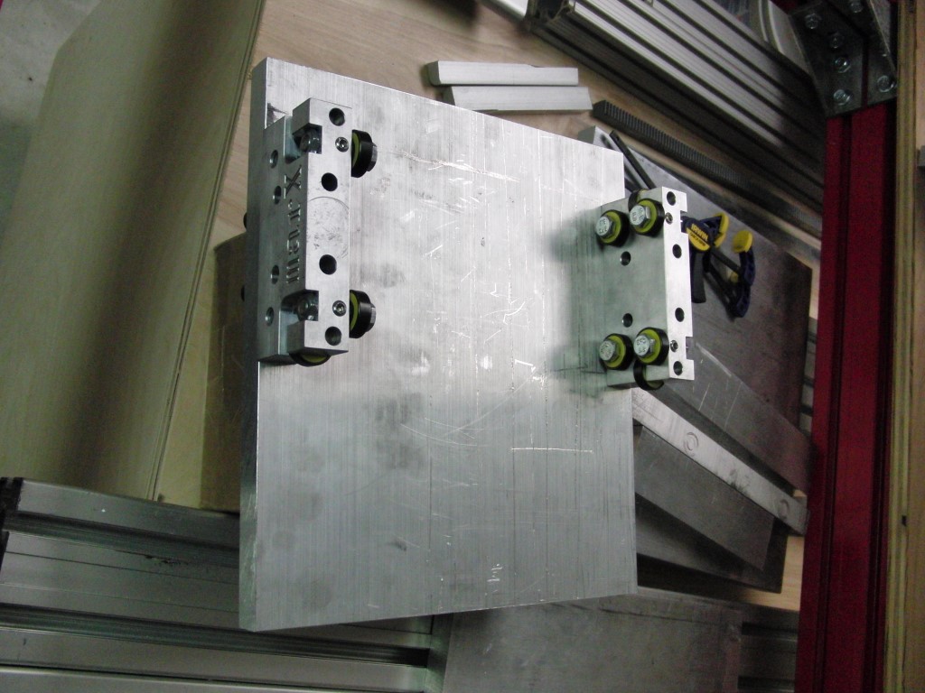
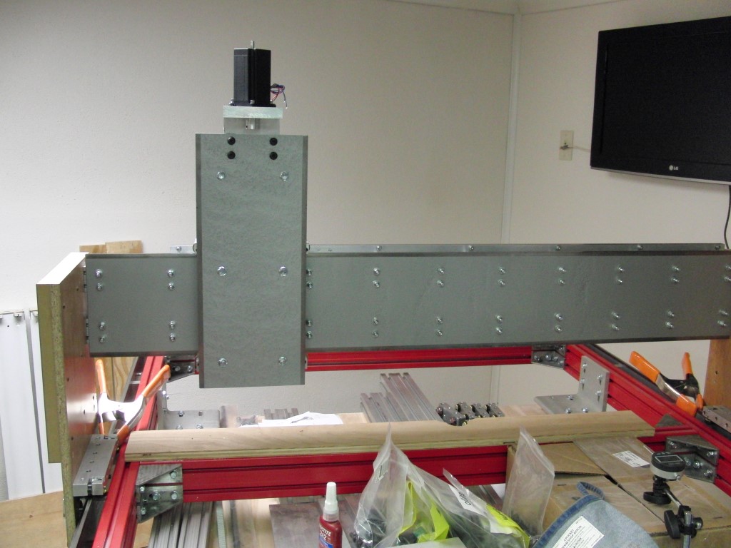
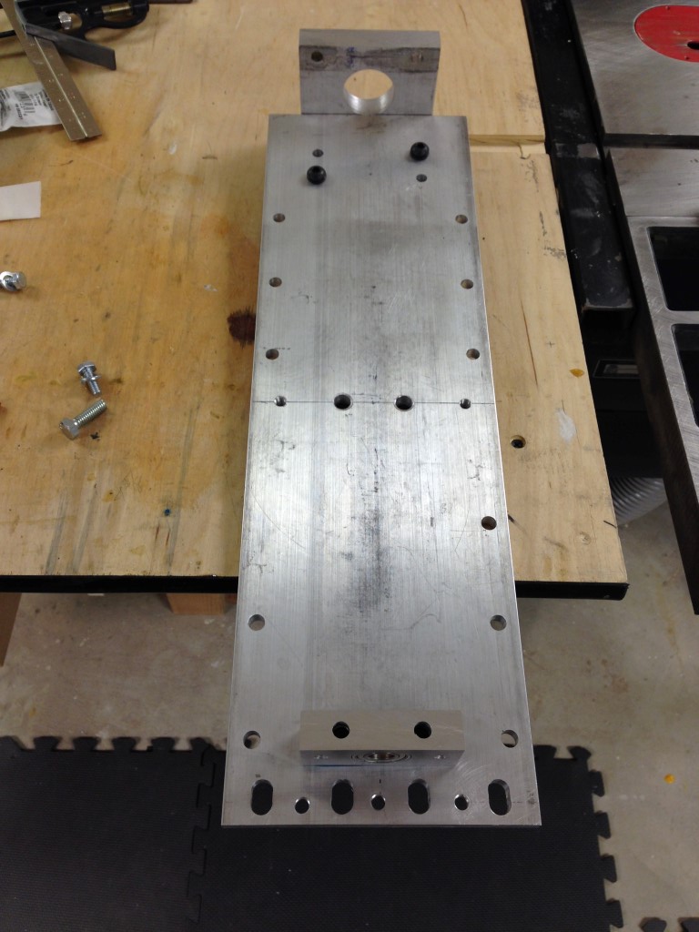
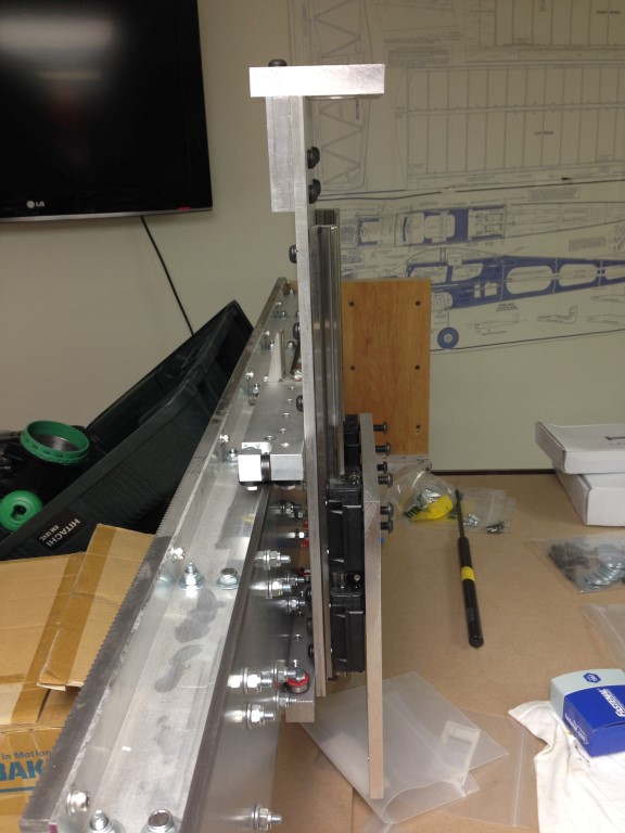
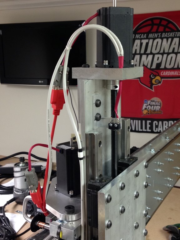
I’ve finally had a little time the last few weekends to make some progress on the remodel of the Z-Axis and thought I would snap a few pics and post them in the thread.
It would have been nice to have been able to cut this plate on a cnc as I had to slot the bottom holes for installation and adjustment, fun with a hand router…
I’m still waiting on the top plate for the motor to arrive but essentially I went with a 3/8″ plate for the back and 1/2″ for the front – it will have about 6 1/2″ of total movement which should be more than enough for any job I can think of.

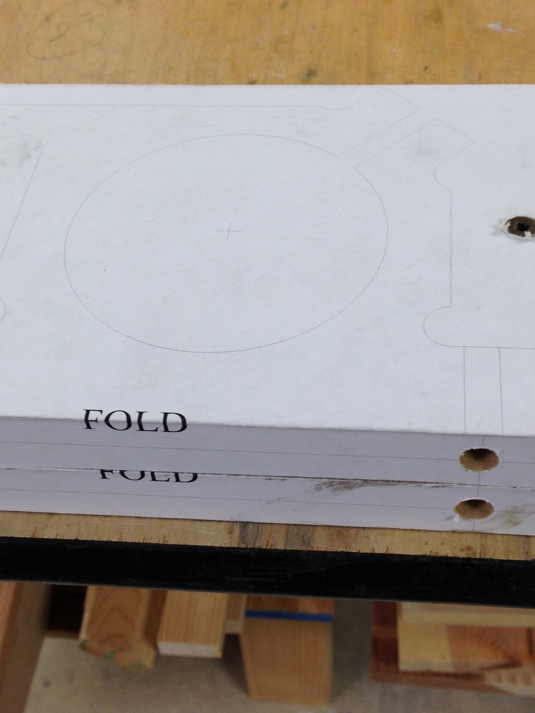
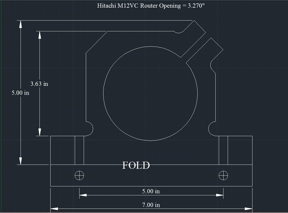
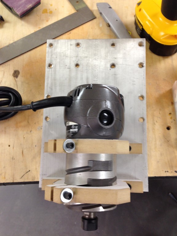
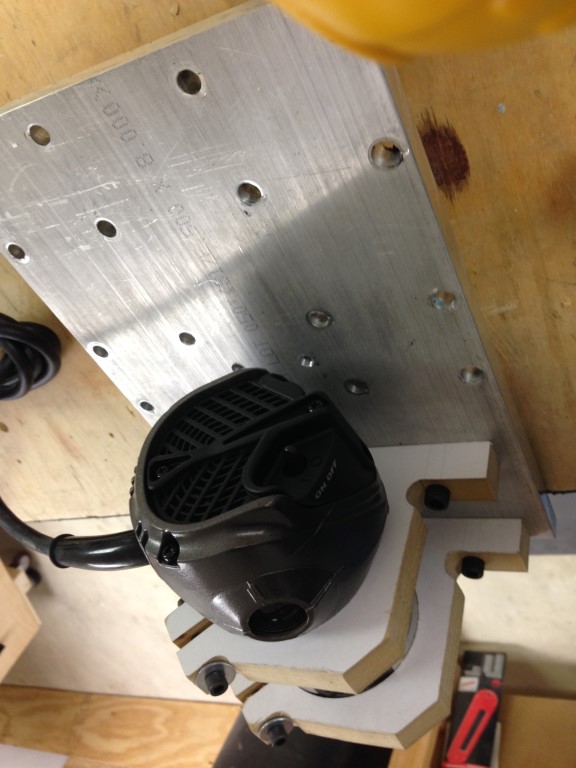
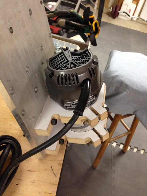
I also drew up a motor mount in AutoCad that would fit my Hitachi MV2 router. Since I don’t have a router to mill the part I’ll have to cut them out of MDF and mill something out of aluminum later. I printed off some template guides and glued them down for fabricating, made the job much easier.. You can download the file if your interested from here, (Hitachi M12VC router plate_mod2) this really was my first AutoCad drawing based upon someone else s design, hopefully I’ll get better with time.
I’m making some solid progress this past week with the Z axis, just about finished, I need to start the wiring and get the limit switches in place.

Ahren, at CNCRouterParts was kind enough to swap out my original 5 start Acme nut (plus the difference in price) which was way too tight upon trial fitting with one of their new designs, much smoother and was a bolt in replacement for the old one with some slight modification to the width.
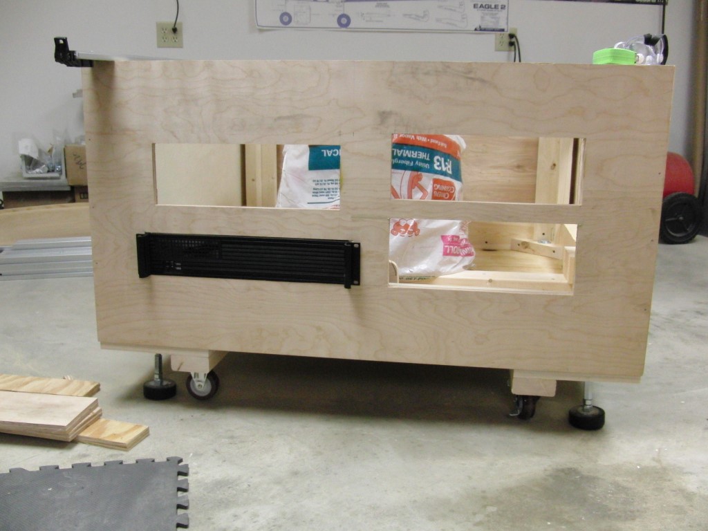
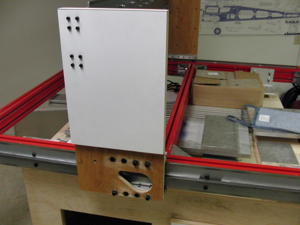
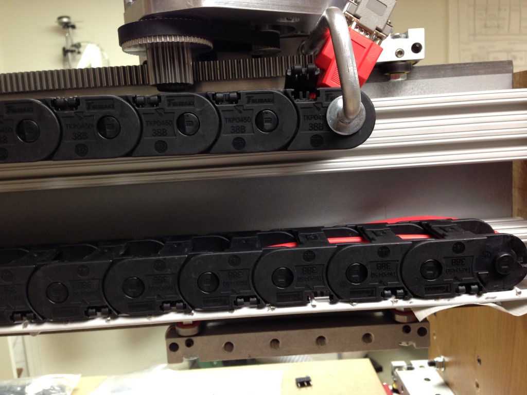
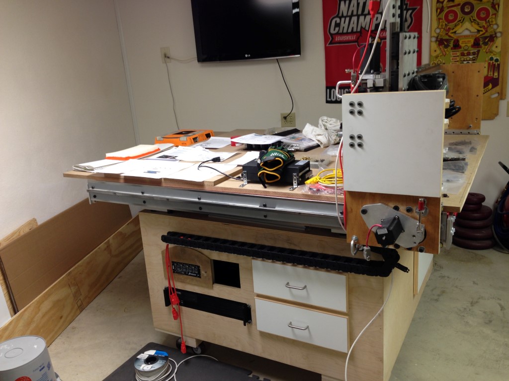
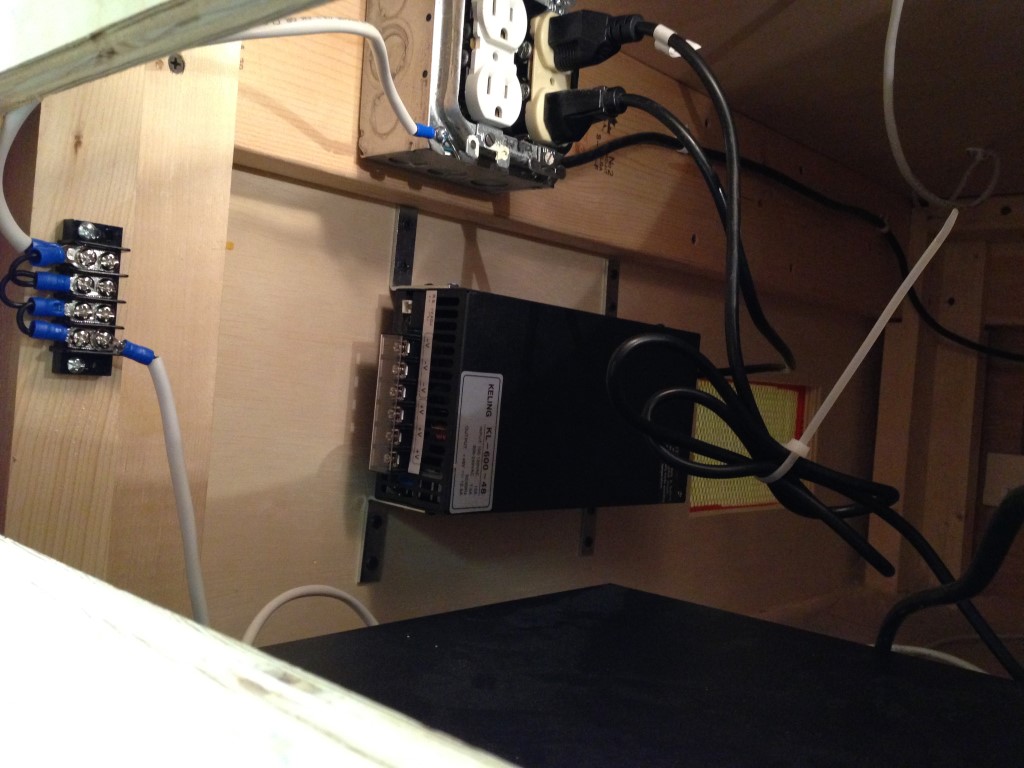
I mounted the PC in the base unit, it still needs some ventilation and I need a mounting plate for the G540, power supply… etc… etc…I also finally figured out the configuration for the echain.. I need to make the connections permanent and then install the limit switches, wire it up and turn it on???
Can I really be that close… hmmm….
**WIRING**
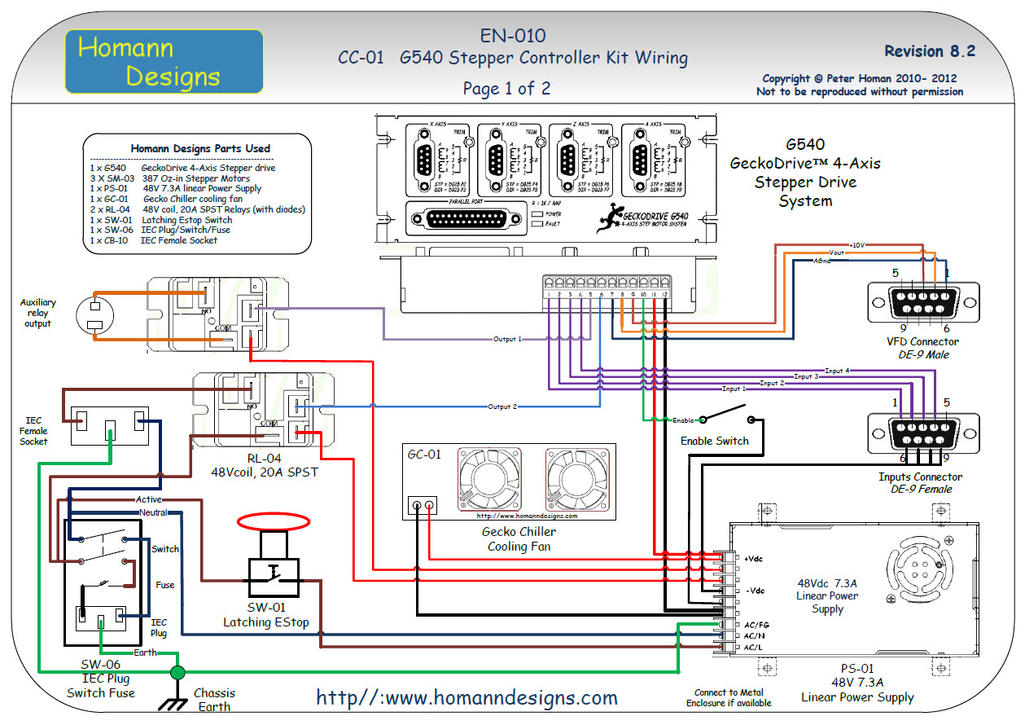
So, I have some wiring questions, actually a lot of questions, hopefully this is harder to write than it is to do. I’ve been reading and saving some docs and I think that I’m going to follow “Peter Homan’s” write up (see attached).
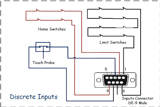
1) Limit switches (NC) – it appears from the doc I can wire all Limit switches in Series. I’m also assuming 2 switches per axis. If they are in series how does Mach know what axis has been tripped?
2) Home switches – it appears these are also wired in Series?
3) E-Stop – His doc has an E-Stop and a “Enable Switch” is it necessary to have both? Can I put the E-Stop in place of the “Enable Switch” is that low voltage?
4) E-Stop – Is the design of the E-Stop to break ground between the PS and G540?
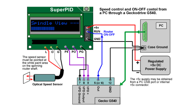
5) From a basic standpoint of manually starting the router that the attached image will suffice for the initial hookup?
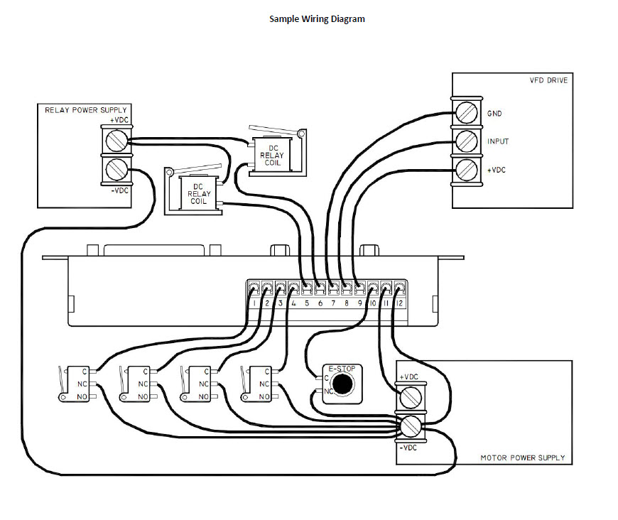
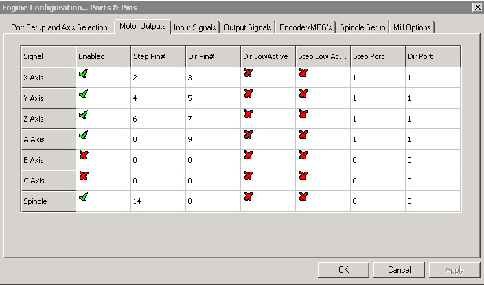
6) I was taking a look this morning at the G540 manual “Sample Wiring Diagram” and I am not sure what the usage of the DC relay’s are for?
7) If my above statement is correct then is there a limit to the number of relay’s you can use – since there are only 2 pins (5 and 6) do they need a separate pin per relay?
8) Further reviewing Peter’s drawing and I think it might be incorrect as on p.1 he’s wired pin 1-4 from the G540 to a DE-9 Female (image) but on p.2 where the male connector connects (image) he only has pins 1-3 utilized, what happened to pin4??
9) How does wiring the Limit and Home switches work in this fashion? Does Mach know what axis just hit the limit what does it do, very confused here…
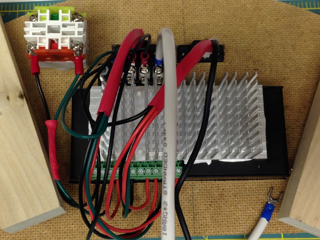
I also believe I’ve figured out the wiring for the Super PID, looks like its a plug in on ports 7,8 and 9… signaled by pin 5 or6.
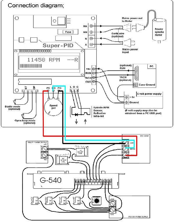
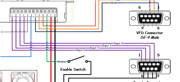
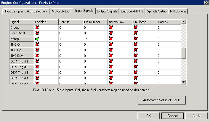
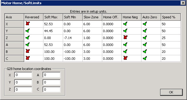
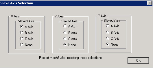
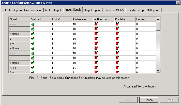
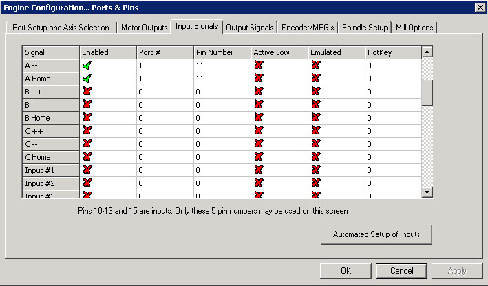
So if I understand correctly.. If I want to “Home” both X-axis and A-axis, which I think makes sense based on my CNC design, they will require “Input1” and “Input2”. “Input3” can be used for the other limit switches which can be wired in Series which leaves “Input4” open, this is how I will be wiring my machine.
Just to spell it out as clearly as possible, in my design “All” the X-Axis stop limit switches are wired in series to a single pin on the G540 all the Y-Axis stop limit switches are wired to a single pin on the G540 and the 2 stop limit switches on the Z-Axis are wired to a single pin on the G540. In total this uses 3 input pins on the G540 and leaves a 4th for a probe for later use.
We’re off and wiring!!
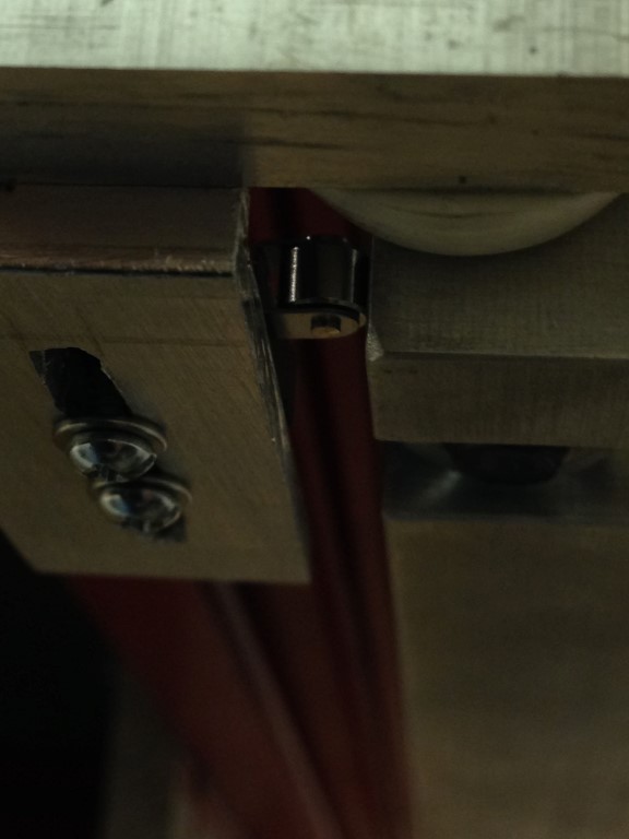
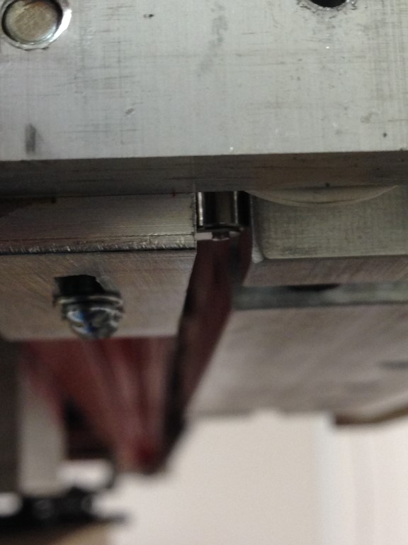
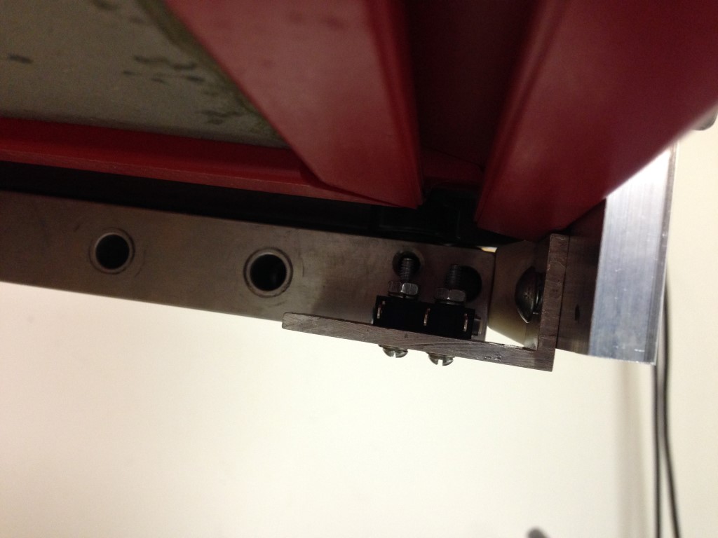
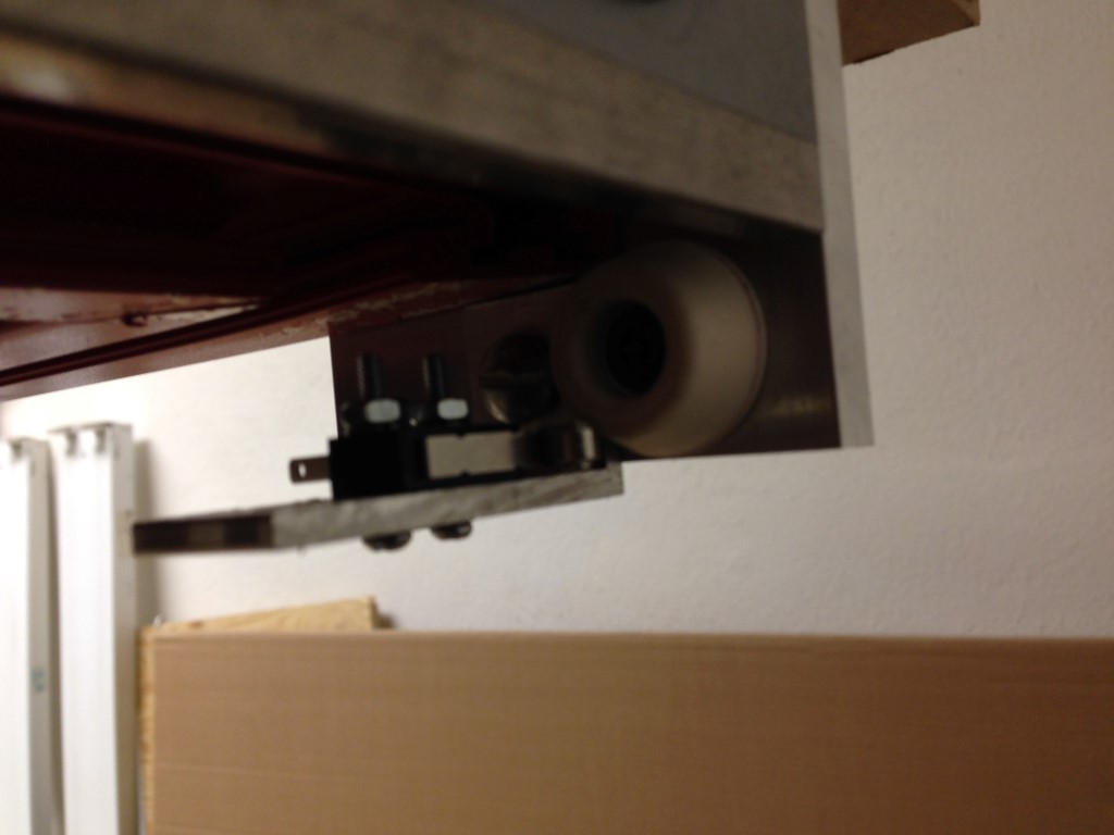
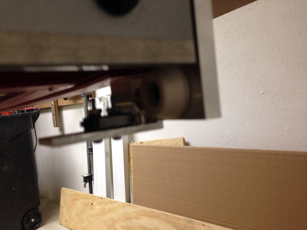
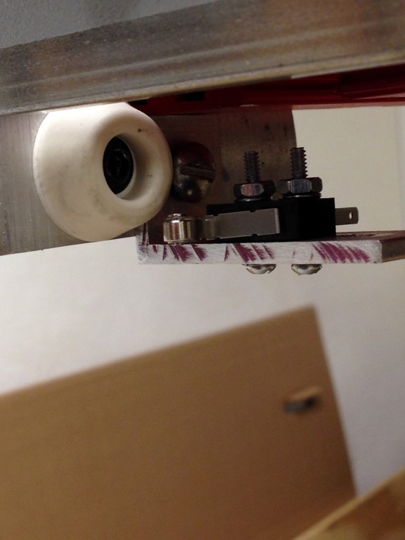
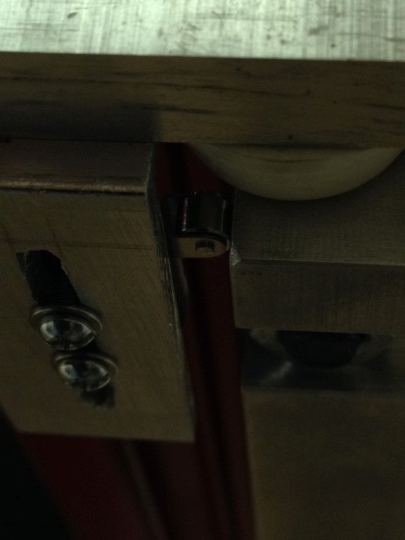
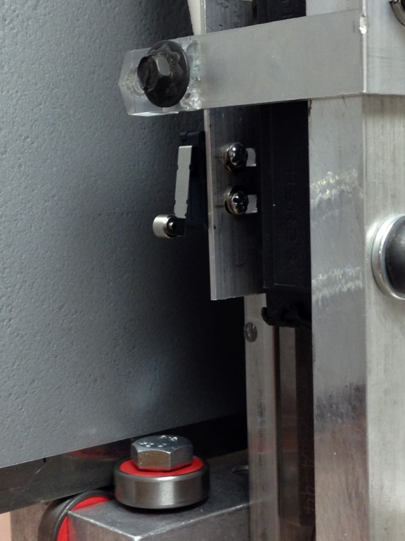
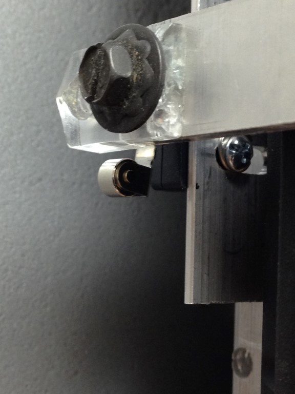
The switches are tripped by the carriages on each Axis. I had to manufacture some adjusting brackets so they could be adjusted for finer movement but in actuality close seems to be good, the key is that they must be repeatable.
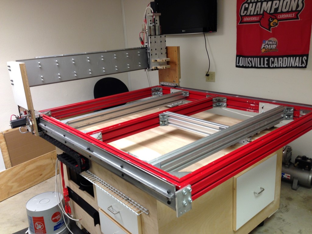
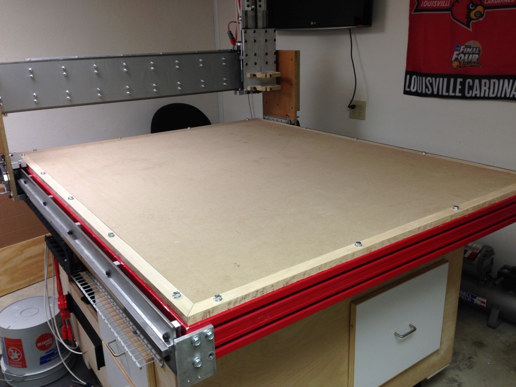
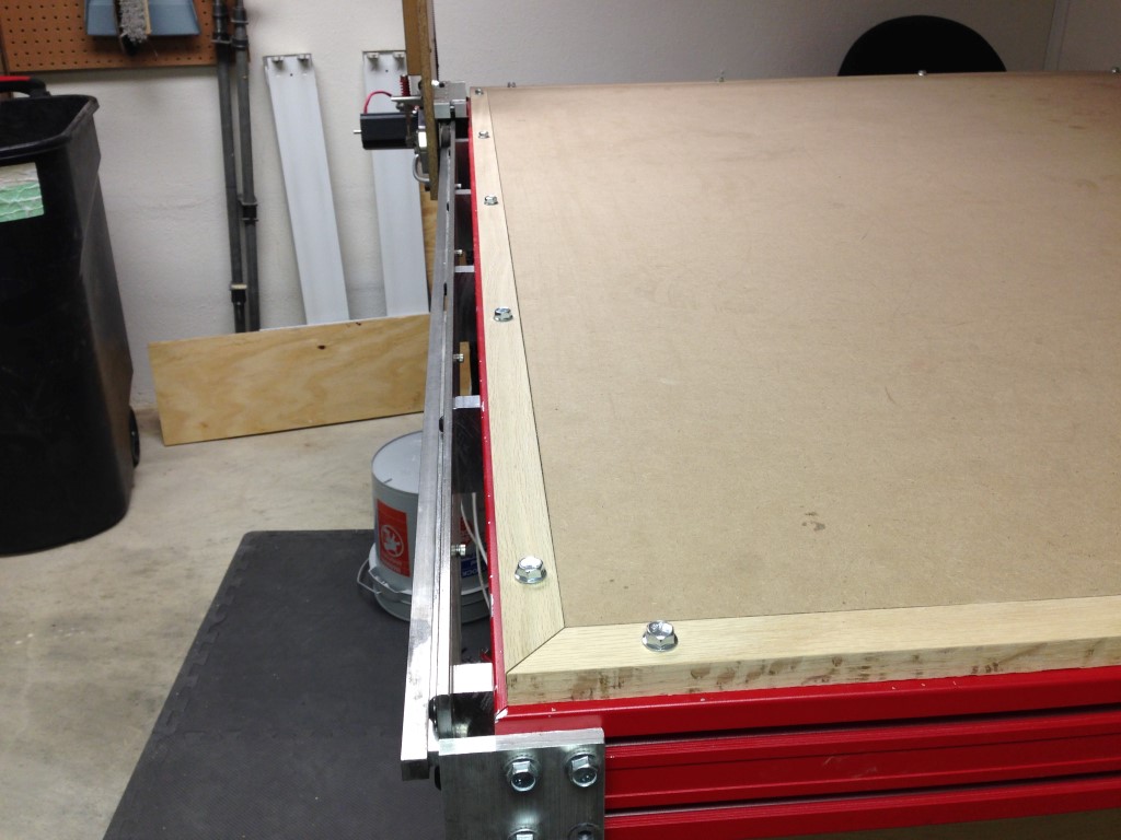
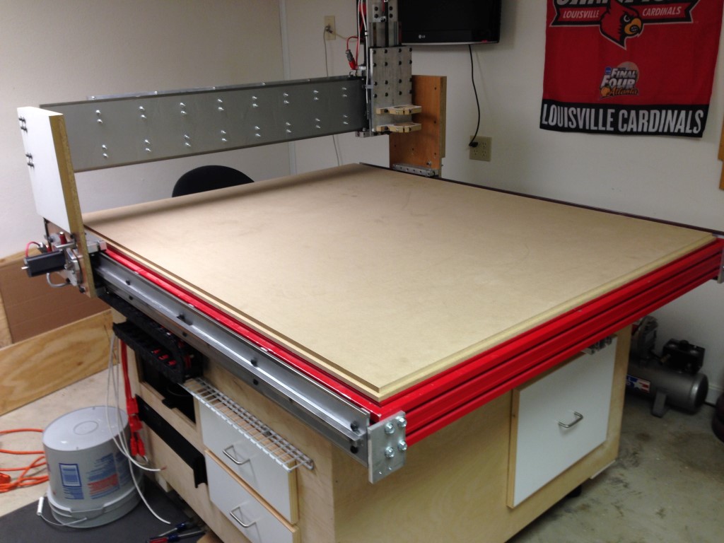
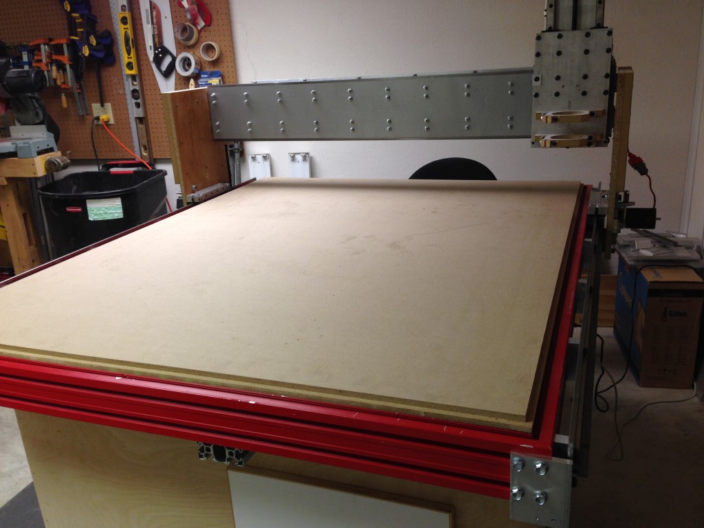
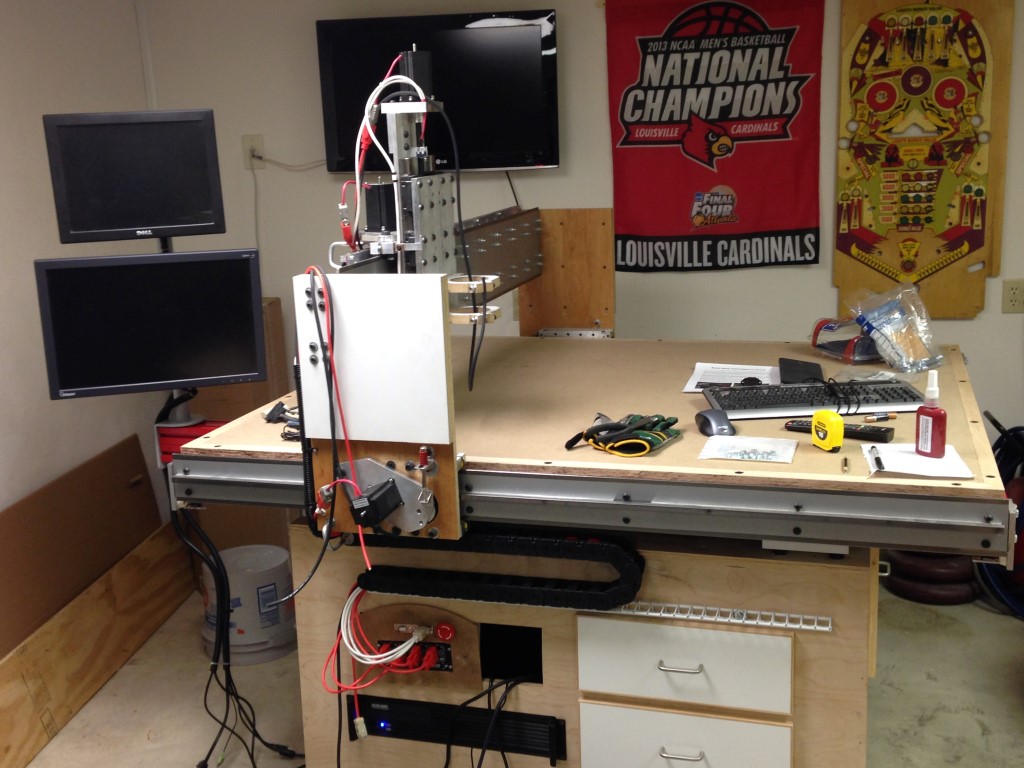
I got started and made some progress with the spoil board and added some additional bracing for vertical work in the future.
The additional bracing should help with warpage of the spoil board since its MDF as well as give a mounting surface for jigs in the future like a fourth axis or for vertical work, not sure…
The switch wiring is complete and just needs to be tied up at the G540 / control panel its been tied and wire loomed and tested for travel and any kinks.
The spoil board was mounted with serrated bolts and probably will be changed since they aren’t counter sunk, well see how it goes. I can see the bolts being a problem with handling material but they were on hand..
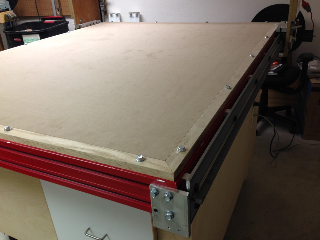
This should be getting close to the last of the build.. there’s still a lot of little things to do and upgrades to make once in place but in general I’m over all pleased with how the project has come out.
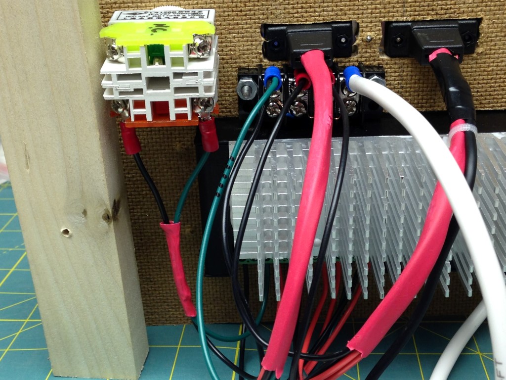
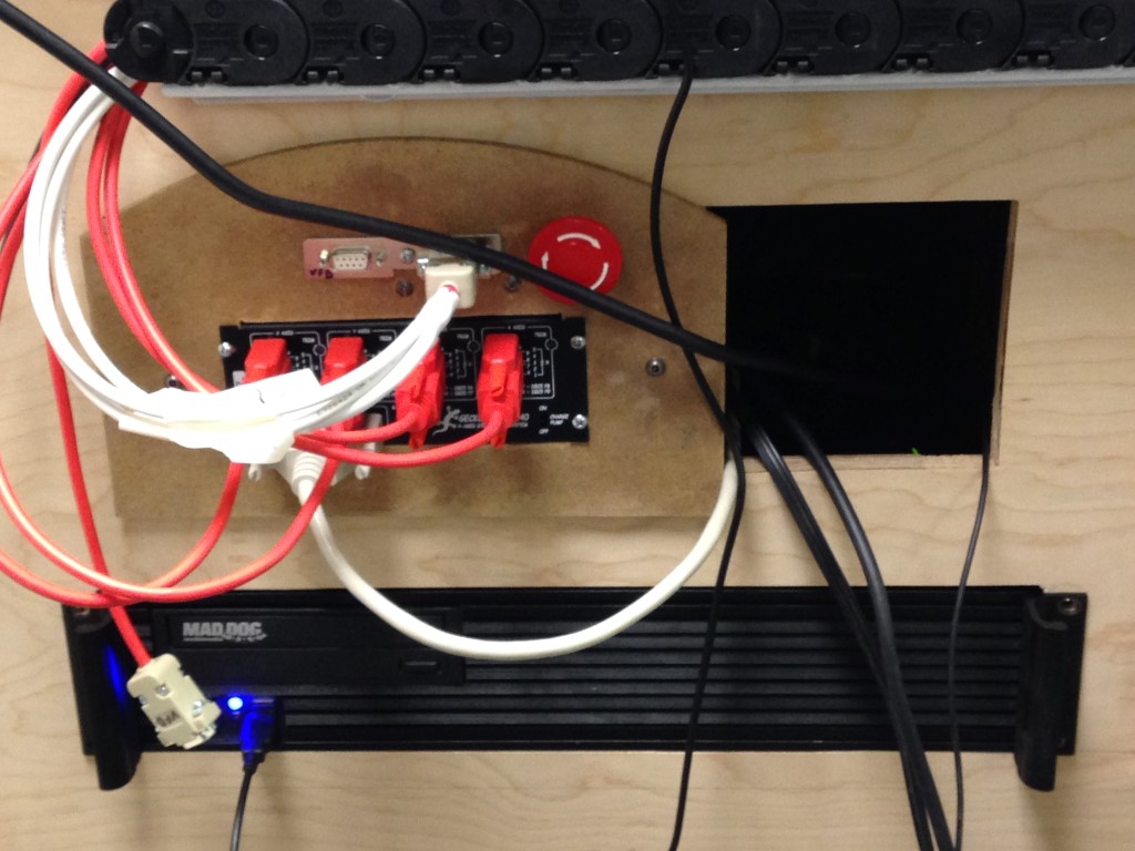
Here are few pics of the G540 wiring, doesn’t mean much and its all going to be redone later.. nothing earth shattering as most of the progress was made by reading the G540 manual and bugging Val with some SuperPID questions that will be folded in later.
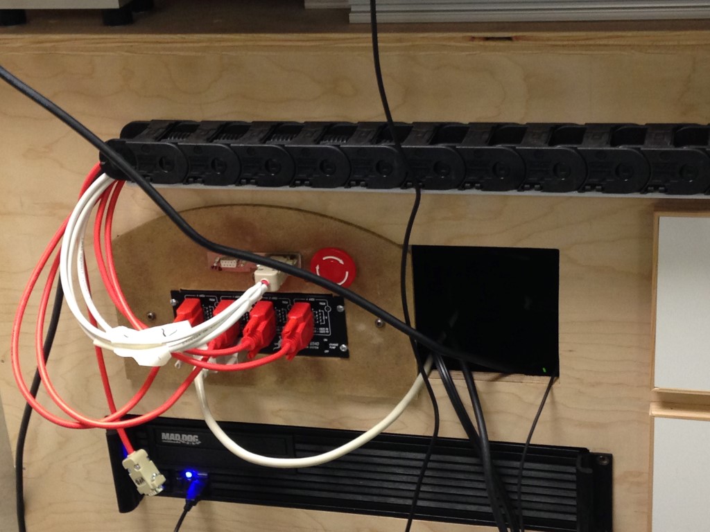
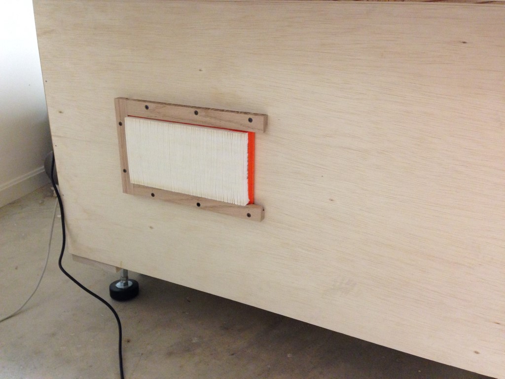
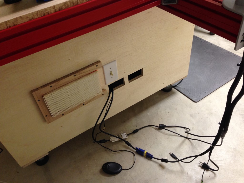
Since this is somewhat of a sealed enclosure I cut a vent in the back and added some filtering.. once the front plate is completed it will house a fan for drawing cooling air into the base of the cabinet.
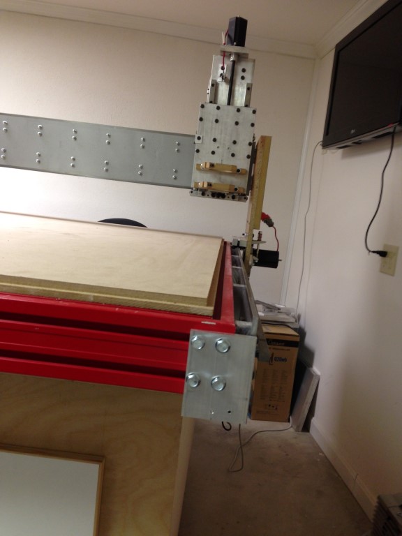
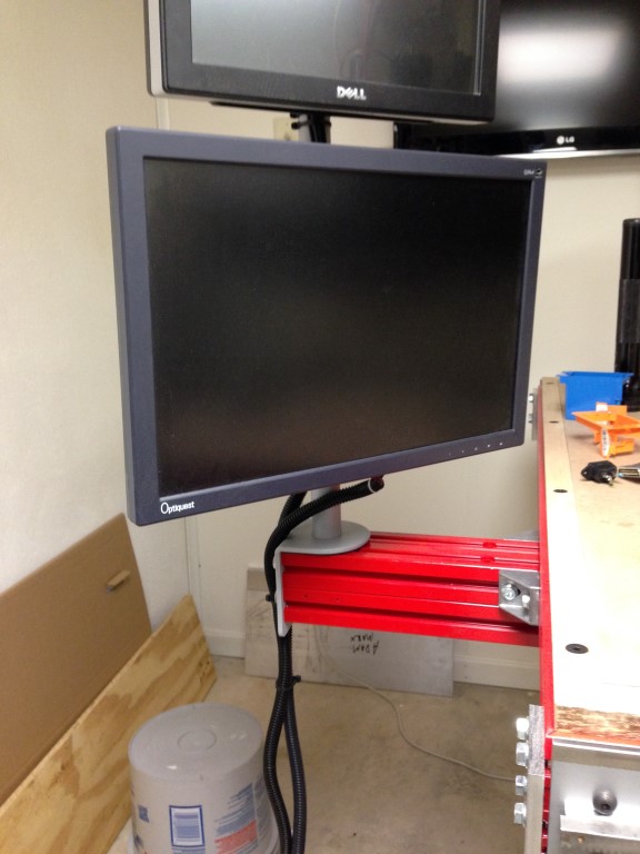
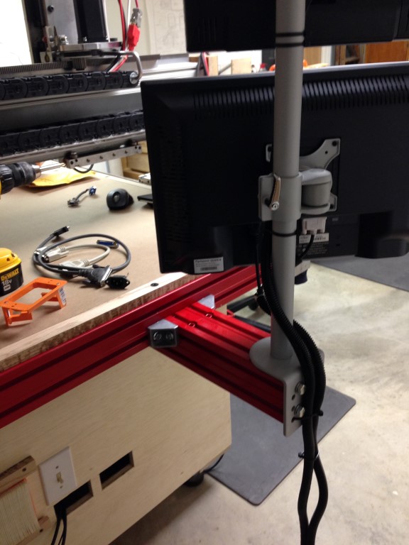
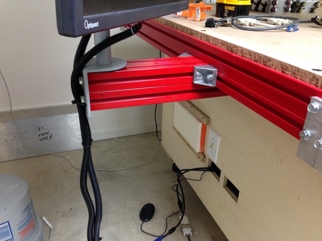
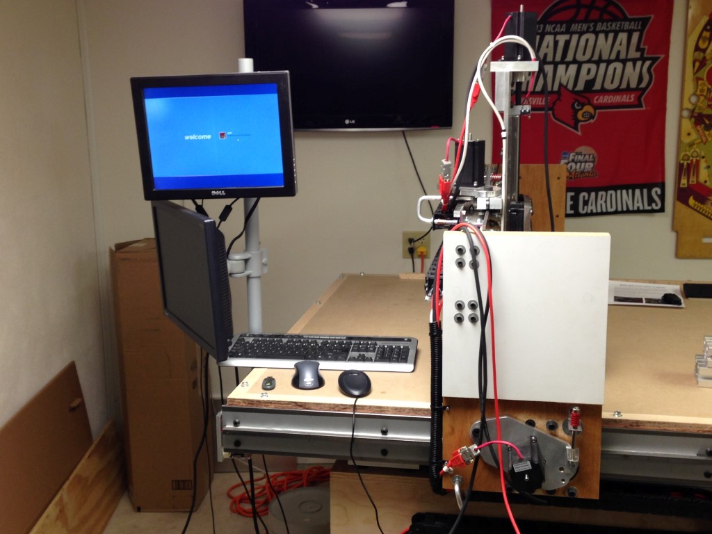
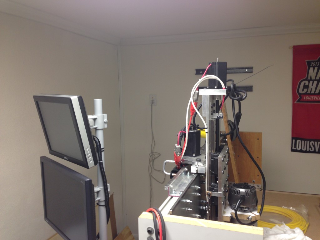
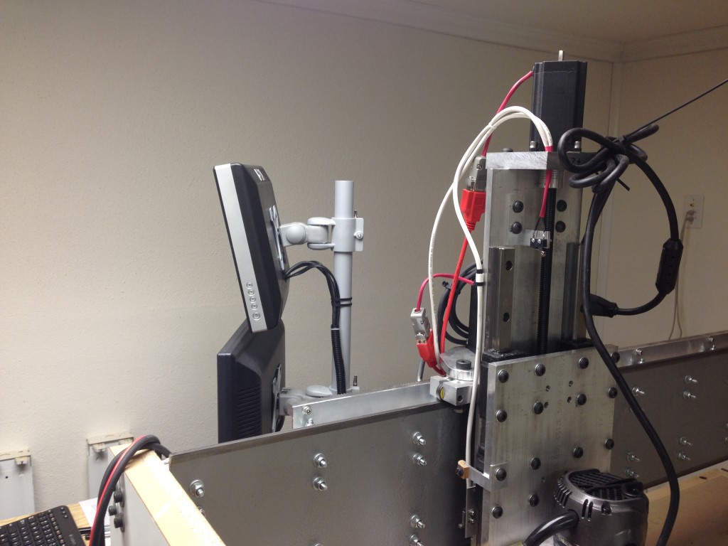
From a hardware side I mounted a monitor arm with dual screens, the top screen is a Dell touch screen. Initially I mounted the arm directly to the frame but soon realized that it was in a bad spot so I manufactured an arm to extend it off the table, its better but not what I would call optimum. I’ll see how it goes after a bit of cutting and what not.
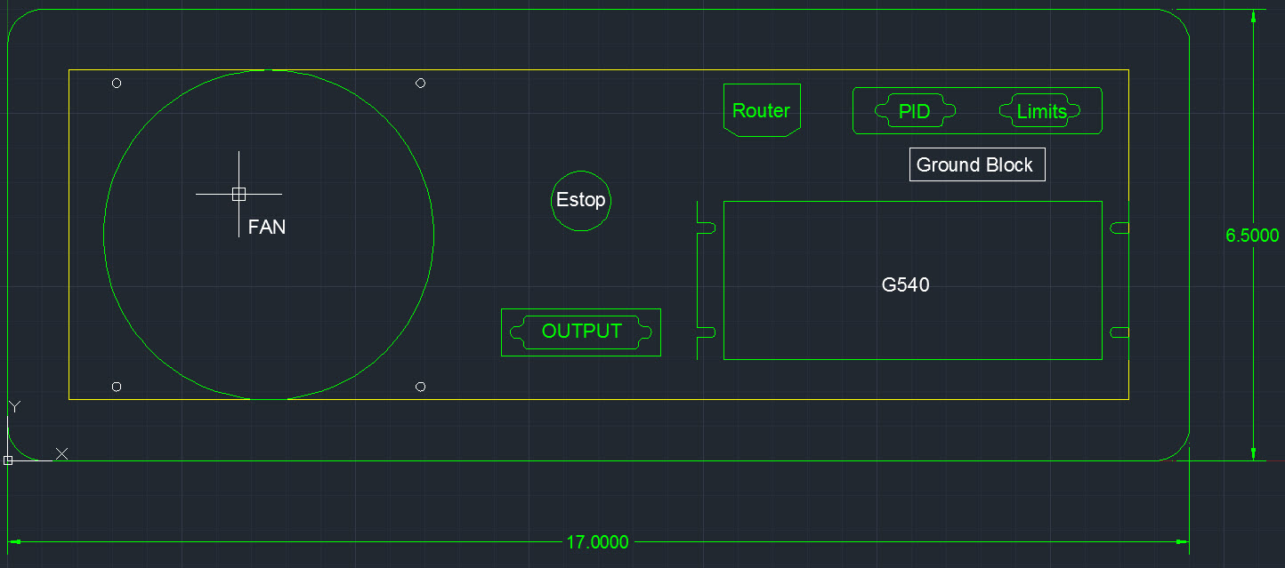
I’ve started working on the front control panel (Control_Panel_radius2) I plan to cut this from some aluminum later.
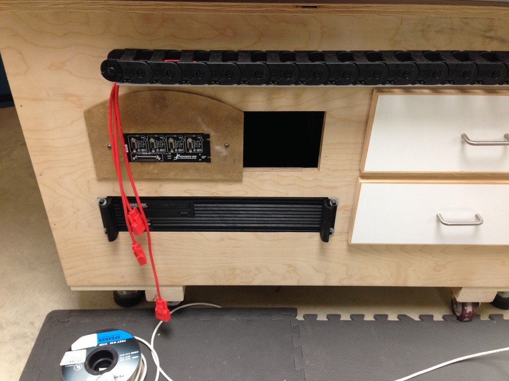
I’ve also cut some access holes for PC connectors and will be cutting a couple of plates shortly to clean that mess up but for now its wired up and working fine. I then finished off the wire mess with some wire loom I had laying around.
After the monitors were mounted it was time to fire it up.. first I needed to get Mach setup and I needed some help with that. I watched the video’s on Mach’s website but I still had some unanswered questions and things I needed cleared up. So this thread (Another sPID, G540, and Mach wiring question for the wiring challenged..) was extremely helpful in getting the initial setup going with the G540, Mach3 and my Steppers. I really appreciate the help from Spk64 and RicknBeachcrest for getting me over the hump. I plan on posting my final setup and screens at the end of this thread for comparison sake.
With the G540 and Mach somewhat together it was time to fire it up.. I was careful to double check my work and that the eStop was functioning, safety first… just in case. If your interested the videos are below.
Well there was no “Magic” white smoke.. sweet!!!
After firing it up for the first time this led to the discovery of the Z axis being too stiff at full extension which led to the dis-assembly of the axis. I essentially moved the anti-backlash nut further up the plate re-assembled the axis and she was smooth as silk. The other small tidbit of information was the I had to make small adjustments to the Axis potentiometer on the G540, its the small opening on the front of the controller, Z needed a little tweaking since the Z was so stiff it needed a little more torque.
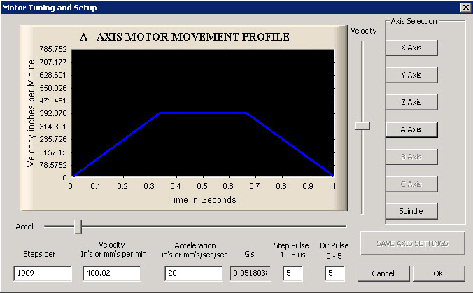
So, next on the list – draw/cut something but first I needed to test my home and limit switches, they seem to check out.. but after making an attempt to jog the machine I realized I was still missing something… I needed to “Tune” the motors, what its not a “plug-n-play”, damn! Oh well a chance to learn more… cool!!
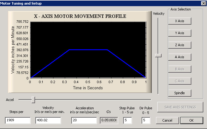
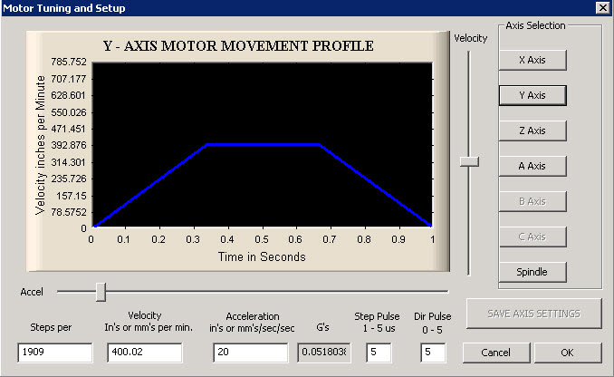
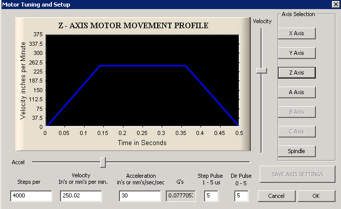
This thread Feeds and Speed and Plunge rates… was an eye opener and many thanks to Ger21 and louieatienza for getting me through it… In the end this turned out to be a Stepper tuning class for me, my take away is that you need to start with calculating the steps for your machine and its particular hardware, from there get in the ball park for Velocity and Acceleration and then tune it from there, read the thread…
Adam,
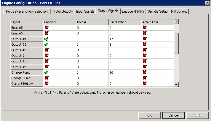
I wanted to finish posting my completed configuration from Mach as I said I would earlier in the thread in case it can be of use to someone later on down the line experiencing some of the same problems that I encountered, the screen shots are of the final settings that I’m currently using.
In is a thread I posted on DIY CNC Router Table Machines I was able to get some help from Gerry and Lee on squaring my X and Y axis, much appreciated the help. The lesson learned here is to have move able switches and use some scrap when making test runs. Alignment issues?
Here is another thread on the terrible racket the motors were making initially before I tuned them. Its a very important part of setting up the motors, the tuning process. In my case this was accomplished with the G540 and the small potentiometers on the front and following the guidelines in the manual and the thread here. Growling machine on first trial run… gah!
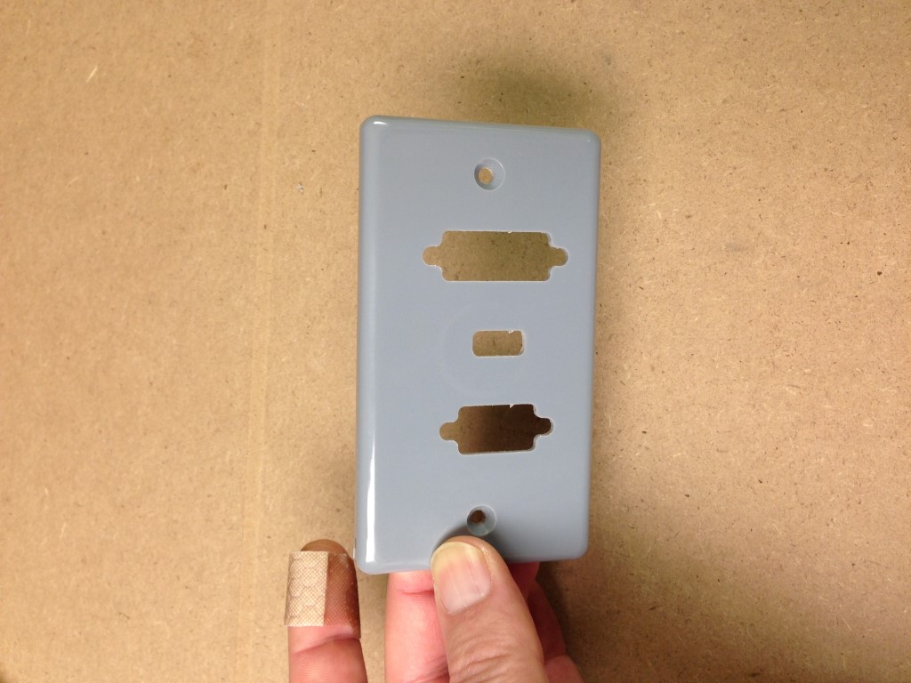
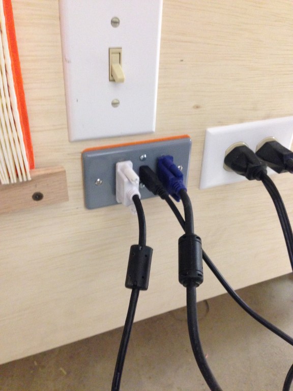
With the above completed I now have a viable machine to run some projects on.. The first test was a trim plate for my video cables. I took a blank plastic cover plate and essentially mounted it and and let er’ rip.. it came out rather well.. very small piece completed and a very happy owner!!!
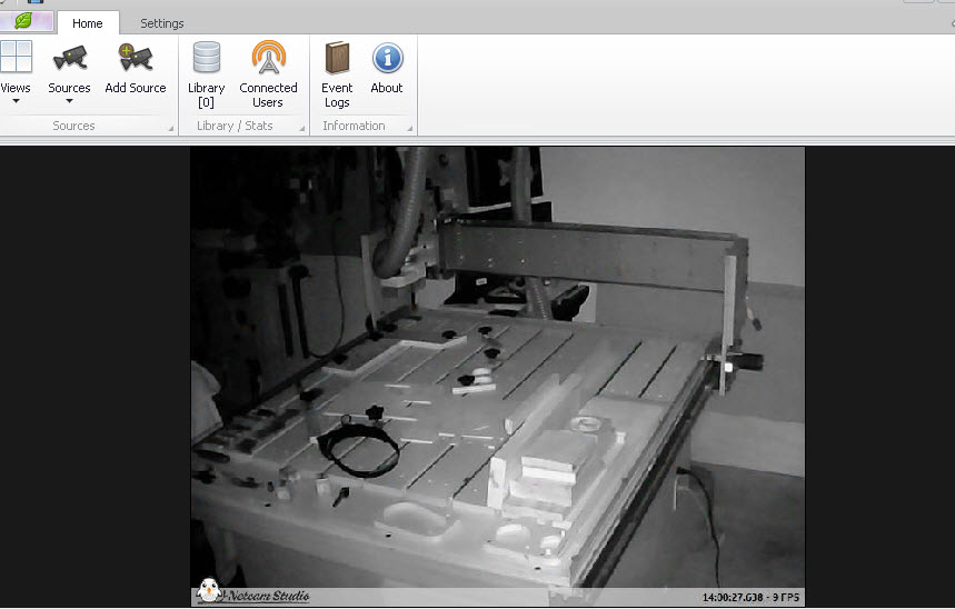
So I installed an IP Camera to watch long jobs, sorry its only private but here is a screenshot in a no light situation, very impressive if you ask me. I reworked the camera a little, a Geeya 720p for POE (power over Ethernet) since I didn’t also want to have to run a power line to the camera. Anyhoo, it works great and is accessible from my iPhone and any browser.
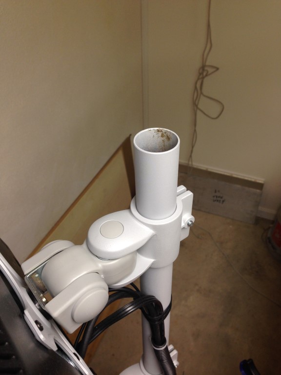
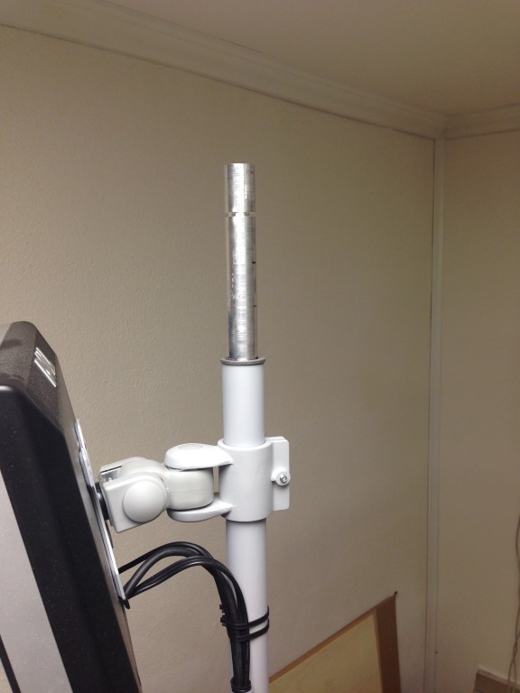
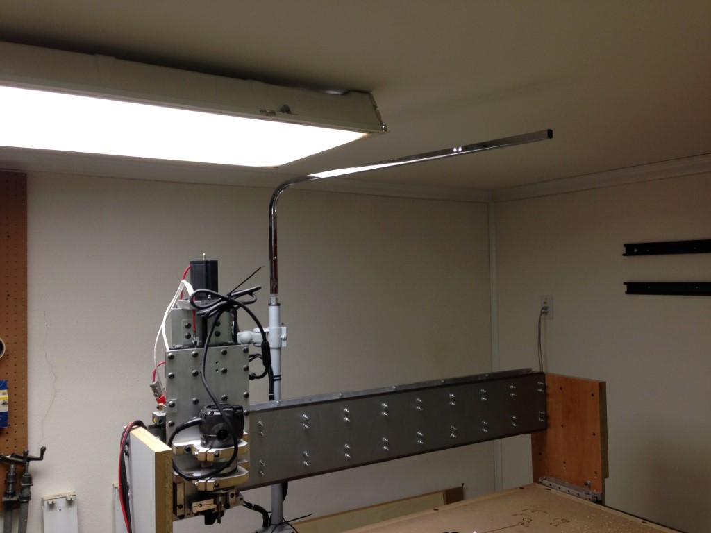
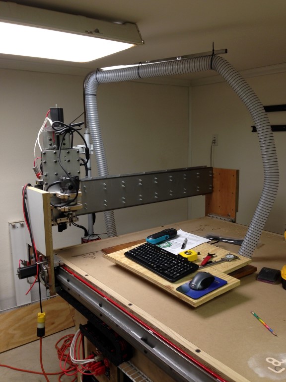
So, I started noodling on how to do dust collection and landed on needing a support arm for the dust collection hose, I currently have a large dust collector and just figure I’ll adapt to the 2 1/2″ hose, we’ll see.
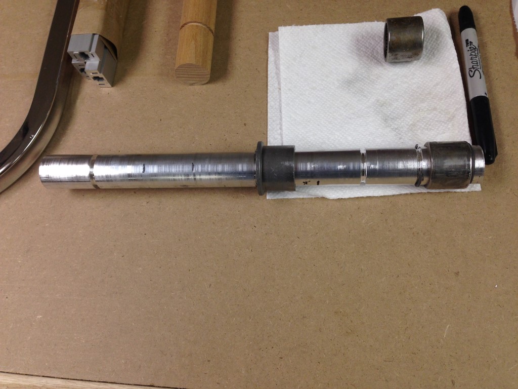
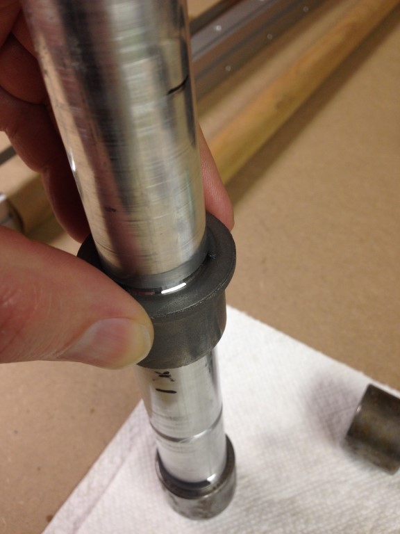
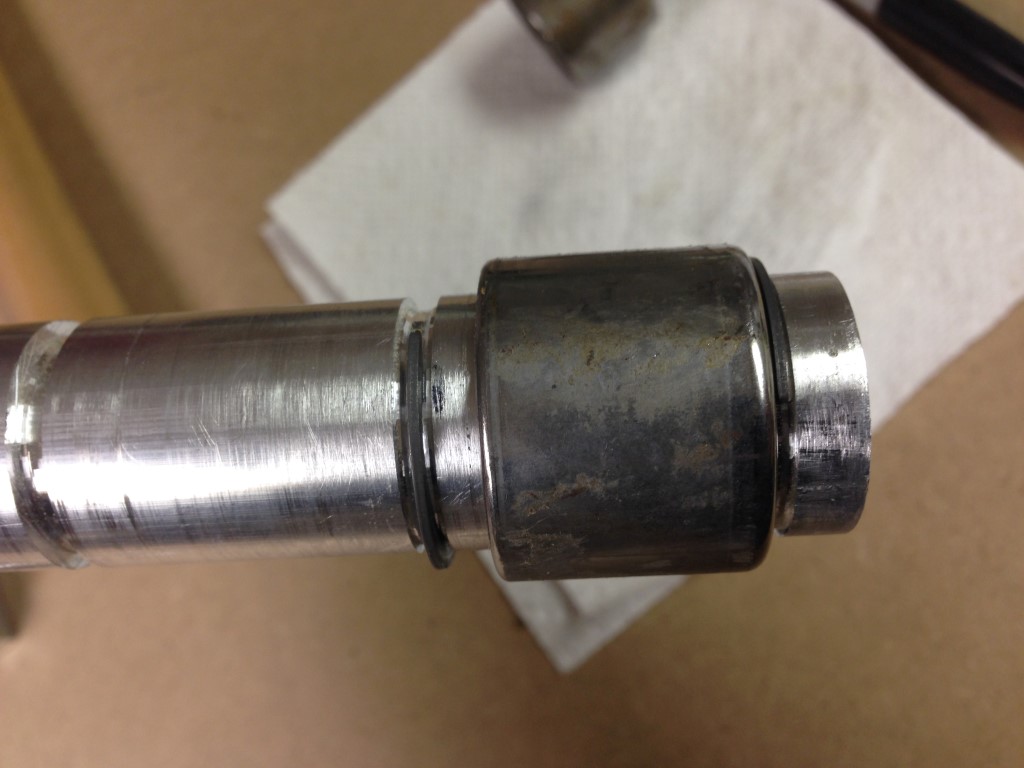
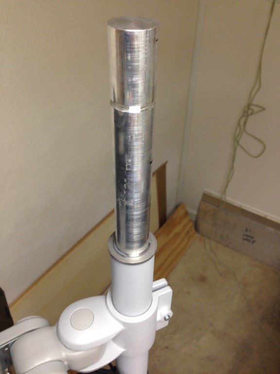
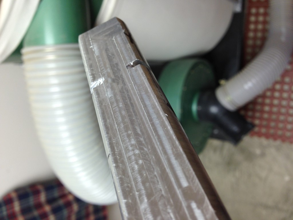
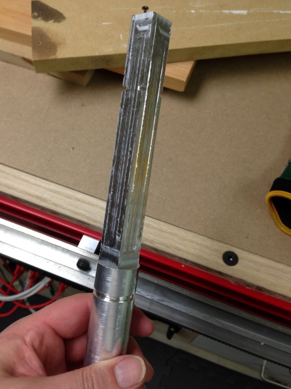
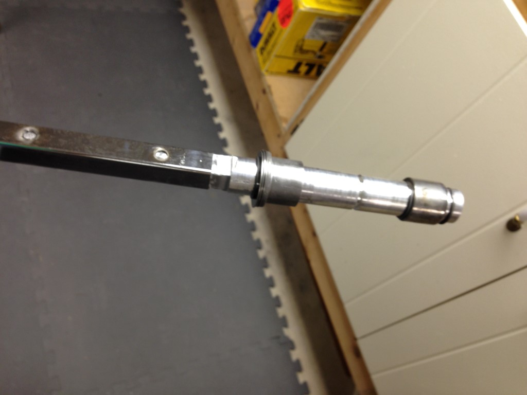
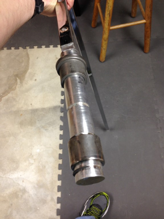
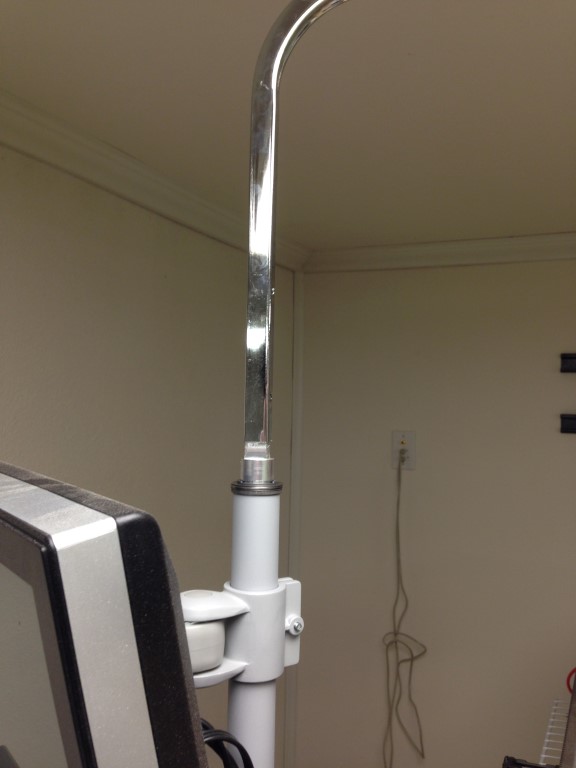
The first step was configuring a rotating post for the arm I already had lying around, 3/4 by 3/4 thin steel and seems to be sturdy enough for hanging a hose on it, perfect. Since my monitors are on a support arm at the rear of my router, I wanted to use that post, I think it will make a good pivot point. I’ve currently fabricated a pivot that will work by using a needle bearing, 1″ piece of 6061 and a bronze flanged bearing.
I’m sure I missed some details in this post so feel free to post questions and I’ll see if I can help. Hopefully you’ve enjoyed reading this as much as I’ve had making my CNC…
If I was able to help you figure out and fix your problem, buy me a beer! and Thanks..
![]()
A masterpiece Adam. Brilliant educationsl set of photo sequences. You have a high tech basement workshop now. I have a messy bench. Peter